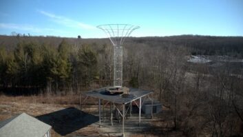
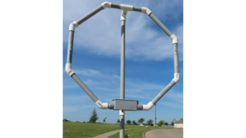
(click thumbnail)Shown, a typical directional antenna common point bus and network. Photo by Cris Alexander.Next to the transmitter compatibility issue, antenna compatibility is the biggest obstacle that AM stations wishing to convert to HD Radio operation must overcome.
In some cases, the cost of making the antenna system IBOC-compatible may exceed the HD-R equipment costs. A well-designed and maintained antenna system may be good to go for IBOC already, but it is likely that at least some modification will be necessary.
Whether directional or non-directional, Step One is to perform a sweep of the common point or antenna tuning unit input. The sweep should include a span of 30 kHz, from carrier to a point ±15 kHz in 5 kHz (or smaller) increments. This can be done using a synthesizer/detector and impedance bridge or it can be done using a vector network analyzer, power amplifier, directional couplers and RF attenuators. Which method is used is not as important as the results, which will be plotted on a Smith chart and analyzed.
The antenna bandwidth specification for AM HD Radio operation calls for symmetry of the load impedance at ±5 kHz with a VSWR of 1.035:1 or better, ±10 kHz VSWR of 1.20:1 or better, and ±15 kHz VSWR of 1.40:1 or better. A sweep of the antenna input impedance will quickly show whether your antenna system is in compliance with this specification.
Adjusting DAs
If the antenna input sweep shows that the system needs work, a good place to start with directional systems is the antenna tuning unit network inputs. An operating impedance bridge should be used to check the impedance “seen” by each transmission line looking into the ATU.
This is usually a two-person job. One person stays in the transmitter building and tunes out the insertion effect of the bridge, re-establishing licensed parameters on the antenna monitor, while the other goes from tower to tower with the OIB making measurements.
For best impedance bandwidth, it’s important to adjust each ATU for a match to the transmission line that feeds it. Tightly coupled high-power towers will have more effect on impedance bandwidth than lightly coupled low-power towers.
Negative power flow parasitic towers, particularly those with low driving point impedances, can have a great impact on impedance bandwidth of the common point. If you’re not familiar with directional antenna systems and their adjustment and operation, it’s better to leave this procedure to someone who is.
For optimum HD Radio performance, the rotation of the Smith chart plot should be within the transmitter manufacturer’s specification. That optimum orientation is something that the transmitter manufacturer will need to provide, however, it’s likely that some field measurements will have to be made before the manufacturer can give an answer.
The manufacturer likely knows what the optimum orientation is at the power amplifier (module) output, but the phase shift through the combiner(s), filter(s) and output-matching network for a given frequency and transmitter may not be known. The manufacturer may have you measure this with an oscilloscope and a pair of 100X probes.
Unless you find your antenna to be within the specification and at the proper orientation, it is likely that you will have to hire a consulting engineer to evaluate the data along with the existing antenna phasing/coupling system design and make some recommendations. This will be money well spent, and as it may take awhile, it is essential that you do this very early in the conversion process. In fact, it should be done before you order any other equipment, in case you find that your antenna system cannot be made HD Radio-compatible.
Got a suggestion for a future topic? E-mail [email protected].