Condenser microphones have been around since the early days of telephone technology, but their high impedance and low output made them impractical.
The first high-quality, wide-range condenser microphone was patented by Edward Wente at Bell Laboratories in 1916, making this year a century since his invention.
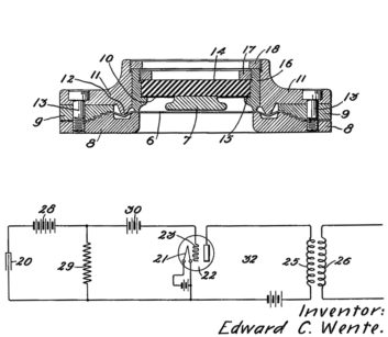
Fig. 1, taken directly from his application, No. 1,333,744, shows the “transmitter,” as it was then called, in a working system with a triode electron tube amplifier. His filing notes that the design could respond to frequencies of more than 16,000 cycles per second (Hz).
The cutaway view of Fig. 1 shows an ultrathin diaphragm, originally steel, stretched in front of a specially-designed back plate. The backplate receives a fixed charge through a large resistance (hundreds or thousands of megohms) from a high voltage supply of 200 volts.
Since the air-dielectric capacitor formed by the diaphragm and the back plate has a bias voltage across it, motion due to impinging sound waves causes a change in capacitance that produces a minute alternating current into the amplifier stage.
Over the next few years, Wente replaced the diaphragm with a lower-mass aluminum alloy and made other improvements to his transmitter design, resulting in the famous model 394 condenser microphone element. By the mid-1920s, refinements in vacuum tube amplifiers made the condenser microphone not only practical, but a state-of-the-art for sound pickup.
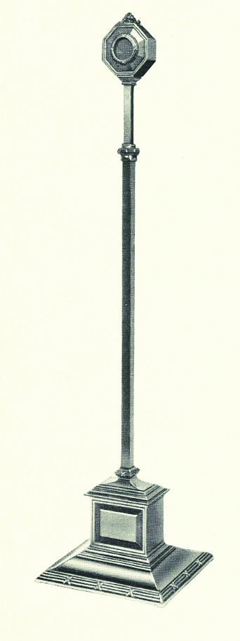
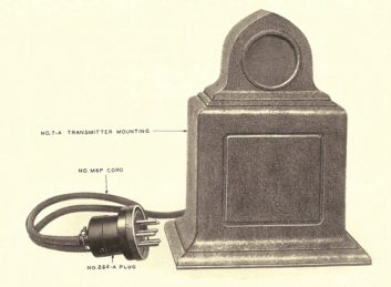
His condenser element was implemented by Western Electric in no less than six distinct models, from the model 7-A “mantle clock” desk microphone, Fig. 2 above, to an elegant floor standing microphone, Fig. 3, right, in pictures from a 1927 Western Electric instruction manual.
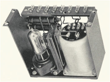
Each had an integrated one-tube amplifier, Fig. 4 below, which converted the low-level signal from the capacitive element into a standard mike-level balanced signal.
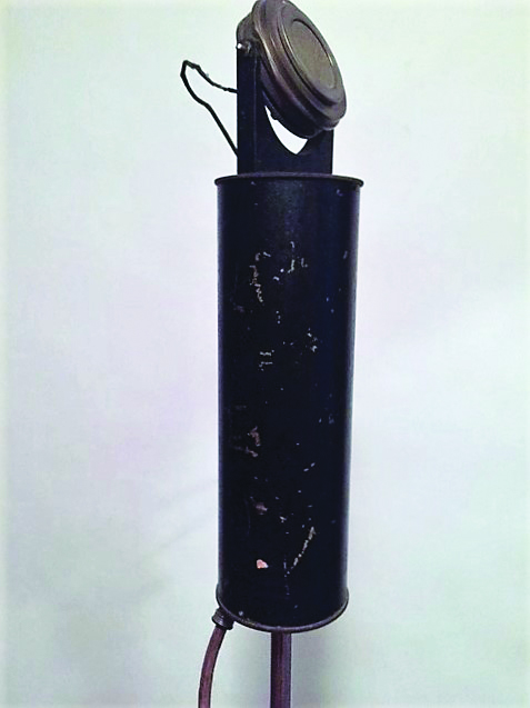
By the late 1920s, these microphones were widely used at movie sound stages, music studios and radio stations. RCA was licensed to manufacture similar condenser microphones based on Wente’s patent, such as the hanging-cylinder style shown in Fig. 5.
Besides the vacuum tube amplifier and impedance converter, the high-voltage supply needed to polarize the condenser element made condenser microphones more costly than carbon mics of the time.
It was known that some materials could hold a static electrical charge for long periods without an external supply. The material earned the name “electret” from electrostatic and magnet, by which some metals can almost permanently align their magnetic domains.
Electrets are made by melting a suitable dielectric material such as a plastic or wax that contains polar molecules, and then allowing it to re-solidify in a powerful electrostatic field.
Work on the electret condenser microphones dates back to as early as 1928. Eventually, a few microphone models with wax electrets were offered commercially in the late 1930s. (See reference [1] at the end of this article.)
The first large-scale application was during WWII, when wax-electret microphones were used by the Japanese in field telephones and Zero aircraft. Wax-electrets, however, did not did not catch on because their polarizing charge would not hold for long and their small capacitance complicated mic preamp design.
Work continued in electret transducer technology and once again Bell Labs achieved a breakthrough in 1961 with a type of precharged dielectric film, of Teflon or Mylar. The film was deposited with a metalized coating to form the capacitive diaphragm [2]. Its low mass provided the high-quality, linear performance of a conventional air-capacitor microphone, but it required no high-voltage supply for bias.
In 1968, Sony brought out the first electret condenser microphone or ECM. From that date forward, ECMs varying in size and cost found enormous acceptance. Today, ECMs are manufactured in countless numbers, ranging from smartphones to top-of-the-line professional microphones.
Examining Low-Cost Electret Transducers
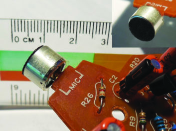
One of the attractions of electret microphones is their low cost. Another is their potentially small size, as shown in Fig. 6 (one in cellphones may be as small as 2 mm in diameter!).
However, the low cost and miniaturization of electret condenser microphones had to wait until the Field Effect Transistor became available (with its extremely high input gate impedance, compared to bipolar transistors) to replace electron-tube impedance converters. The FET allowed Sony (and others) to produce an electret microphone at a price low enough to use with battery-operated recorders.
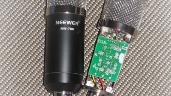
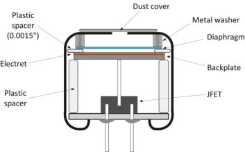
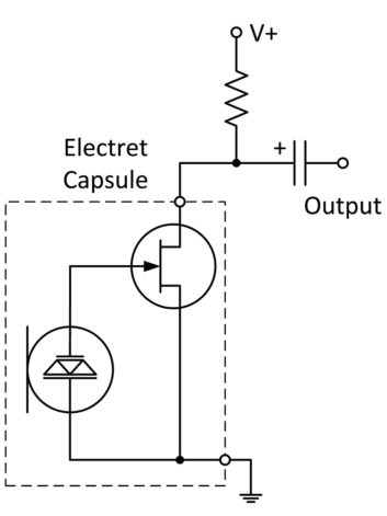
Almost immediately, manufacturers started putting the FET inside the transducer capsule, as shown in Fig. 7.
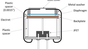
Much like Wente’s model 394, the ECM has a diaphragm suspended above a backplate. A small air gap separates the diaphragm from the backplate, which is insulated from the pressed metal shell. There are two versions of ECMs: one with a precharged electret membrane, a “forward electret” and the other with a non-conductive electret film on the back plate, or “back electret” transducer.
Common to nearly all low-cost ECMs, a junction-type field effect transistor (JFET) is included in the case. The wire to the gate terminal is pressed against the back plate. Usually one terminal, the source, is soldered to a ground trace on the bottom printed circuit board, which is crimped to the metal case. The drain of the JFET is brought out alongside the source wire. Only two connections are involved, enabling a good solution for high volume applications.
An electrical representation of a low-cost ECM is shown in Fig. 8.
The high input impedance of a JFET gate provides a good interface to the capacitive sensor, and the relatively low resistance connected to the drain provides sufficient output drive toward the next stage, often a bipolar transistor. Where immediate digital output is needed, some ECMs are tied directly to an analog-to-digital converter IC. Note that the Drain is connected to an external load resistor of a few kΩ, which is tied to a positive DC supply ranging from 3 to 10 volts.
The method of biasing a JFET with a grounded source and load resistor on the drain is called “phantom biasing.” The gate of a JFET behaves like a reverse biased diode with has some small leakage to ground. This leakage current makes the DC gate voltage settle around 0 V, which is a usable bias condition — to a degree. However, alternating current is supplied to the gate as the sound waves move the diaphragm toward and away from the back plate. Strong sound waves can produce a negative voltage from the diaphragm large enough to be clipped by the reverse leakage.
To put this in numeric terms, international standards have established 1 Pascal (Pa) for specifying the sensitivity of microphones. This is equivalent to a sound pressure level 94 dB SPL. (Interestingly, a 1939 RCA product catalog specified their microphones at 10 dynes/cm2, which is 1 Pa!) A microphone with a specified sensitivity of –42 dB referenced to 1 V/Pa, for example, would produce a voltage of 7.9 mV/Pa:
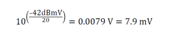
According to DIN standard 45500, the overload limit of the amplifier must, for semi-professional use, be high enough so that an SPL 10 Pa can be handled at less than 1% distortion. This is 10-fold increase in SPL would produce 79 mV of signal voltage. This is clearly a challenge for JFETs that are expected to handle tiny signals with minimal noise.
Sound pressure waves of the opposite polarity can be clipped by the JFET through forward conduction of the gate diode, but this occurs at higher voltages than on the negative side. The result is asymmetrical clipping, which can produce large amounts of odd-order harmonics.
ECM manufacturers try to optimize the electret transducer and the JFET characteristics to minimize distortion. Literature on mic testing shows that, as expected, many ECMs begin overloading above 110 dB SPL, probably due to JFET distortion. The diaphragm itself may be capable of handling SPLs near 130 dB before their motion, and their output signal, become distorted. Unfortunately, phantom biasing, while cheap, has its limitation for high quality sound pickup.
Adding a Third Terminal
The three-terminal electret microphone gets past some of this JFET distortion by using a source follower configuration, which connects the resistor between the source and ground, so the source can follow the gate signal, and the voltage drop across the internal diode can stay relatively constant. But, this configuration lowers the gain of the JFET and sacrifices dynamic range by increasing noise. Manufacturers have also developed chip ICs for consumer devices that have good noise and distortion performance, but include additional low-frequency rolloff to combat vibration and wind noise, making them undesirable for professional use.
As Fig. 8 shows, the ECM comprises a capacitor (the diaphragm/back plate combination) driving a resistive load (the JFET gate). This represents a first-order high pass RC filter. The capacitance of the transducer, C, may be in the range of 30 to 100 picofarads (pF), depending on the diameter and spacing of the backplate from the diaphragm. The input impedance, R, of a typical JFET is around 100 MΩ. The low frequency cutoff can be estimated by:
Fc = 1 / (2 πRC)
= 1 / (6.14 * 100 x106 * 30 x10-12) = 54 Hz
The main noise source in ECMs is semiconductor noise, due to the high input resistance on the JFET. Typical values are as good as –120 dB, which may sound rather low, but if the reference sensitivity of the microphone is –45 dBV, it is only a 75 dB signal to noise ratio (SNR) at the rated sound level of 94 dB SPL. (A piano played moderately might produce this SPL. Conversational speech, on the other hand, might average 60 dBSPL at 1 meter, which would lower the signal to noise ratio by 34 dB, to only 41 dB above program level.)
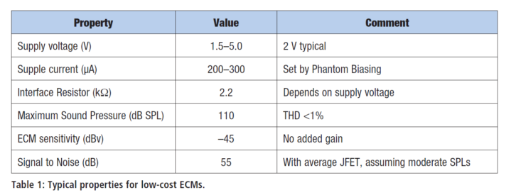
In summary, ECMs provide a compact, low cost solution for microphones. Table 1 shows some typical properties for low-cost ECMs that might be used in cordless phones, audio recorders and computer devices.
What’s Next?
Arguably, we get performance that is entirely adequate for consumer use. For professional use, we would like to see a somewhat high signal-to-noise ratio, to record an orchestra, for example, and a little more headroom for loud bands and singers at close range.
In another article, we will take an inexpensive microphone that is available on the Internet and upgrade it, using an $11 large-diaphragm back-electret capsule and a $5 preamp circuit that is optimized for dynamic range and low distortion. We will also use a computer circuit simulator (that is available free, online) to model the original and upgraded circuit. I think you will like the outcome!
John Kean is a principal engineer with Cavell Mertz & Associates and has a private consulting practice for broadcast audio clients. He is former senior technologist for NPR Labs.
REFERENCES
[1] http://www.acesandeighths.com/microphone_evo.html
and http://www.coutant.org/webster/index.html
[2] https://web.archive.org/web/20120204233550/
and http://www.bell-labs.com/org/1133/Heritage/Foil/