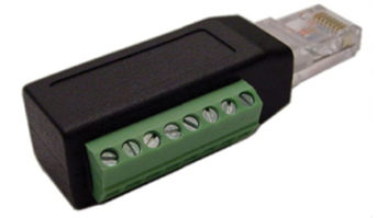
In our March 5 column, Buc Fitch wrote about a simple adaptor that every engineer needs. It’s a simple “H” pad that matches 150-ohm mike level to a 600 ohm line level. Longtime equipment manufacturer Harold Hallikainen (www.hallikainen.com) comments that, although the pad provides a differential gain of –55 dB, its common mode gain is 0 dB. This means the common mode rejection ratio of the input will be 55 dB worse than it was. If the shunt resistor were split, with the center grounded, the common mode and differential mode gains would be the same, maintaining the input CMRR.
Thanks, Harold, for making a good adaptor even better.
* * *
Broadcast engineer Paul Sagi sends in a useful site:
www.mantaro.com/resources/impedance_calculator.htm. It’s a selection of impedance calculators that Mantaro engineers use and freely share. Paul used the twisted pair calculator to calculate impedance for some new UTP cable he used to replace the telephone wiring of his ADSL Internet service. Now the SNR margin is better by 5 to 6 dB with the new cable.
There are calculators for both straight wire and strap, and the calculations make it easy to see why strap is good for high frequency and impulse currents. It’s neater than paralleling many round conductors, although Paul has added some round conductors to fool and satisfy copper thieves, putting the round wires above the strap. You can also use many round wires instead of strap, with the loss of a few to theft not having much effect.
* * *

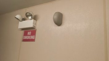
Another example of an old pole, this one in San Bruno, Calif.
It’s not just in the wilds of Montana that sections of wooden phone pole are left hanging until the cables can be transferred!
Dane E. Ericksen, P.E., is a consultant to Hammett & Edison in Sonoma, Calif. Dane just read the April 9 issue of Workbench, and saw Greg Muir’s “old pole” pictures. They reminded him of a similar replacement pole that was at a friend’s house in San Bruno, Calif.
Seen in the image here, it was this way for about six months. The “air pole” made Dane real nervous when the only available parking spot put his car directly below.
* * *
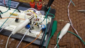
Hal Schardin shares a Pubtech listserv post written by Dave Barnett, who is constructing a building and learned some things about electronic ballasts for fluorescent lights.
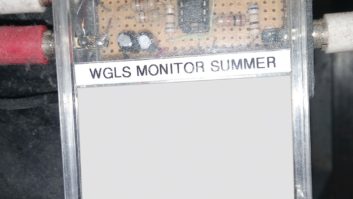
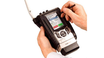
His station monitors an EAS signal that is already pretty weak; any added electronic noise in the facility would be a concern. For standard four-foot light tube applications, Dave tried Philips ballasts that had been specified by the contractor, but found them to be noisy. A single light would render his test radio useless for picking up the EAS primary within 20 feet of the ballast — and plans called for about 30 of these lights in the building.
Dave then tested a similar type of light that uses a GTE Sylvania ballast. By comparison, the radio worked quite well beyond about three feet from the light. He went with that model.
Talking to the light supplier, Dave learned that common fluorescent products use a half-dozen ballast models interchangeably. It’s wise to be aware and try various models.
Dave also tested a dimmable recessed can fluorescent. It produced interference somewhere between the levels generated by the Philips and GTE ballasts for four-foot tubes.
He further tested an LED retrofit for recessed cans, made by Sylvania. It caused no interference even when the radio’s antenna was held up to the light. It fades nicely on a dimmer and is brighter than the incandescent version it replaces. It cost $25; so he has what he needs for the recessed lights.
Another LED-based fixture, made by Lithonia Lighting, replaces a two-tube fluorescent. It looked acceptable and the light was nice and dispersed, so Dave decided to test this too. A local community center has these lights in one of its meeting rooms; Dave took a radio in and asked them to turn on the lights. Ultimate failure! His signal strength meter pegged and the FM signal — way stronger than the EAS primary — went away completely.
The lesson to be learned from Dave’s limited tests is that engineers can expect wide variation in RFI generated by various brands of fixtures and ballasts.
Hal Schardin has been down this road too and writes that if you want lower EMI/RFI from an electronic ballast, specify a “residential” ballast. Ballasts for residential applications must meet the lower consumer limits of EMI/RFI. Electronic ballast emissions are covered by FCC Part 18.
A further lesson: It’s not enough to leave lighting up to the architect or contractor. Engineers should be involved in the entire project from planning to completion.
Hal Schardin is engineering supervisor for the Minnesota State Services for the Blind.
Contribute to Workbench. You’ll help your fellow engineers and qualify for SBE recertification credit. Send Workbench tips to [email protected]. Fax to (603) 472-4944.
Author John Bisset has spent 44 years in the broadcasting industry and is still learning. He handles West Coast sales for the Telos Alliance; he is SBE certified and a past recipient of the SBE Educator of the Year Award.