A Diamond Discone antenna (circled in red) was chosen for off-air monitoring of AM and FM stations. It is mounted along with our microwave antennas on the 160-foot rooftop. I can’t remember a time in my broadcast engineering career when off-air reception has not presented issues in studio buildings and leaseholds. This applies both to station monitoring and EAS reception.
FM reception can be plagued with changing multipath, co- or adjacent-channel interference, intermodulation (IM) products, strong signal overload/desense or a combination of any or all of the above.
AM reception has its own set of issues, with local electrical noise topping the list, followed by shielding from metallic objects, loop directivity (for multiple station reception), IM products, interference, nearby strong signals or any combination of these factors.
In a typical studio setup, reception of multiple signals is required, starting with one’s own signals for confidence monitoring. EAS monitoring can include AM, FM, VHF (for NOAA weather radio broadcasts) and even low-band VHF (as is the case in Los Angeles, where the sheriff’s department is the LP-2). Rooftop space is often limited, and such space in leaseholds can also be expensive. Is it possible to use just one antenna for all the above bands and applications?

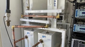
Receive RF distribution system at CBC-Denver. Note the Pixel 12 dB broadband preamp (bottom), the pair of back-to-back AM/FM splitters above (with 20 dB pad between the FM ports) and nine-port splitter above. In the Portable People Meter age, we find ourselves needing to provide dedicated off-air feeds to our PPM monitors. Some keep these monitors at the transmitter site, but I like them in the control rooms, right in front of the operators. In a multi-station cluster, that can mean either a lot of splits from air monitor receivers or a lot of receivers. Is it possible to use just one distribution system for all this?
Or to merge these challenges into one question, is it possible to achieve satisfactory FM, AM, VHF and whatever other reception is needed using a single antenna and distribution system?
That was the challenge we were faced with when building out our new four-station Denver studio facility a few years ago. This facility is in one of the top floors of a high-rise, and we do have some limited rooftop access (but for just one receive antenna).
Reception tasks included our four AM stations with powers ranging from 50 kW to 660 watts, and EAS reception of one AM and one FM station. The list of receivers included DaySequerra M4 HD tuners for the four off-air monitors, a TFT AM receiver for the EAS LP-1, a Tascam FM receiver for reception and a Sangean AM/FM tuner for utility off-air monitoring in the engineering room (the Sangean tuner really counts as two tuners since it has separate AM and FM antenna ports).
This image shows AM spectrum right off the antenna …
(Click to Enlarge)… and this is AM spectrum with the preamp. Note the noise floor is just below peak of carrier.
(Click to Enlarge)ANTENNA OPTIONS


Considering my options for a single receive antenna, I knew I could not use a loop. It wouldn’t work for FM in any event and with the AM sites spread around, some would be in the nulls while others would be in the lobes. We had to have an omnidirectional antenna, one that was broadband enough to give good performance on both the AM and FM bands.
After much deliberation, I settled on a Diamond D-130J Discone antenna. The specifications show that it will work from 25 to 1300 MHz, but I have used these antennas for AM reception before with good results. I was crossing my fingers that with the elevated (160-foot) rooftop mounting location, it would provide for adequate AM reception at this new facility.
A quick check with a FIM showed signal levels in the –60 to –30 dBm range right off the antenna, which should be plenty.
We used RG-8X coaxial cable for the 50-foot run from the antenna to the engineering room below and connected that to a broadband nine-port 6 dB splitter. That got everything working with adequate signal, day and night, except for our lowest-power AM station, which is just seven miles from the studio location. That one was in and out. The issue was simply weak signal, on the order of –70 dBm after line and splitter losses. We lived with it for a while, but knew we would have to do something to improve reception.
ATTENUATING PREAMP
I was visiting with Tom Walker of iBiquity Digital sometime later and the conversation turned to off-air reception. I asked Tom what iBiquity uses at its monitor locations for broadband amplifiers. He recommended a unit made by Pixel Technologies out of Golden, Colo., right in our backyard, so we ordered one, picked it up at the factory to save shipping costs and brought it over to try. The unit is a model MBA-12 and has 12 dB gain from 0.5 to 2400 MHz. It is powered through the coax by a power injector (sold separately).
With great expectations, we connected the preamp input directly to the feedline from the antenna and connected the output to the splitter input. Powering the unit up, we routed the utility receiver to the shop speakers and … nothing! No signals on any band. It was as if a 60 dB attenuator had been placed in line with the antenna.
Just to make sure, I bypassed the preamp (keeping the same cables in place just in case one of them was the problem) and everything came back. We put the preamp back in and again it killed reception completely.
Preamp full-range spectrum shot right off the antenna. Note the very high signals at the top end of the FM band.
(Click to Enlarge) Next, I got out the spectrum analyzer and connected it to the preamp output. That’s when we began figuring things out. The noise floor, which was at about –105 dBm off the antenna, rose to –60 with the preamplifier in line. The signals compressed into the noise. In essence, we had a broadband attenuator/noise generator.

With the analyzer again connected to the feedline from the antenna (no preamp), I did a sweep of the whole passband of the preamp, 500 kHz to 2.4 GHz, then did a peak-find with a marker to see if there were any exceptionally high signals. I suspected that perhaps KOA, the 50 kW AM flamethrower just a few miles south of our studio location, was overloading the preamp and making it do funny things. I was on the right track but had the wrong station.
The peak-find took me to two FM signals at 101.5 and 107.1 MHz, both in the –20 dBm range, way over the –30 dBm maximum input of the preamplifier. I thought those two rim-shot FMs were way the heck and gone east of town on a 2,000 foot tower. A little research revealed that while their main transmitter site was far out, there were a pair of 20 kW boosters just a few blocks north of our studio. Either one of those strong signals would have given the preamp trouble, but both together … Wow!
Clearly I needed to find a way to notch those signals. I started with some resistive inline coaxial attenuators that I use with the network analyzer, stacking them in series with the preamp input while watching the preamp output with the amplifier. I found that with right at 20 dB of attenuation, the noise floor fell back to –105. That, then, was the “magic number” I was looking for. We needed 20 dB of notch on those two FMs.
Here’s our weakest signal after the preamp with the bandpass and attenuator.
(Click to Enlarge)A SIMPLE AND ELEGANT SOLUTION

I looked at inline tuned filters, but found them either too expensive or too big. On a whim, I decided to try something different. We didn’t have any reception issues with the LP-2 FM we monitor (on Squaw Mountain, some 11,400 feet AMSL), so I could stand some attenuation across the whole FM band.
After a bit of searching, I found that Pixel also sells a band-filtered AM-FM splitter, normally used to split the feed from an antenna to the AM and FM antenna inputs of a multiband tuner. Could I possibly use a pair of those back-to-back in series with the antenna lead, with a 20 dB pad between the FM ports to provide 20 dB of attenuation on just the FM band?
I tried it and voila — it worked! Plenty of FM signal for our purposes (–60 dBm +/-) and a great-looking AM spectrum! Our weakest signal came up to –45 dBm and the noise floor was at a tolerable –95 dBm, providing 50 dB S/N on our most challenging signal — after the splitter. That station now has a full and robust HD lock on the studio monitor.
The combination of the Diamond antenna and Pixel preamp is a hands-down winner, one that I will undoubtedly use in our many other facilities. And if we have FM overload issues, I can repeat my band attenuation trick. If the problem is strong AM stations, I can just as easily attenuate the AM band and leave the FM band alone.
Every situation is different, and the combination of antenna, coax, preamp and splitter that we chose may not work in every situation, but there is a good combination of choices for most every application. Careful planning and some experimentation should get you where you need to be.
W.C. “Cris” Alexander is director of engineering at Crawford Broadcasting Co.
Share your attenuation solutions with us. Write to [email protected].