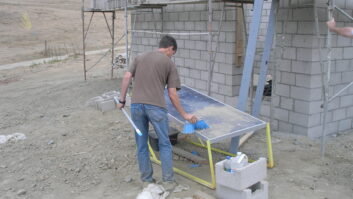
(click thumbnail)Two skirted towers on Mt. Scott in Portland, Ore. The left tower supports an FM antenna and serves as an AM radiator. The wireless tower on the right also supports a one-bay FM aux antenna.This is the last in a series of articles on shared use of transmitter sites. The previous part appeared in the Feb. 1 issue.
For the past several months, we have taken a hard look at just about all the aspects of co-locating broadcast transmitting facilities with other broadcast and non-broadcast transmitting facilities.
In today’s tight tower space market, co-location is sometimes the only reasonable solution for a station seeking a new home.
In this, the final installment of the series, we will wrap up our look at using an existing FM, TV or wireless tower as an AM radiator, discussing skirting, tuning, guy wire considerations, bandwidth and lease elements.
Making it work
An ideal AM radiator generally is an insulated tower, meaning that both the tower base pier and guy wires are insulated from the tower structure, electrically isolating the tower from ground and other conducting objects and structures.
An ideal AM radiator also features a 90-degree, 120-radial buried copper ground system. Take a look at just about any FM, TV or wireless tower and there are two things you generally won’t find: insulators and ground radials.
A couple of thoughts come to mind: it can’t be easy to insulate an existing tower, and plowing in a ground system in the presence of streets and buildings is tough. These factors do not necessarily disqualify its use, however. In many cases, creative engineering can be employed to make such a tower work as a perfectly acceptable AM radiator.
We dealt with options for ground systems in the previous part of this series, so we’ll set our focus this time on using a non-insulated (or grounded-base) tower as an AM radiator.
Years ago, the FCC allowed shunt-fed towers to be used as AM radiators. In this case, a grounded-base tower was fed with a slant wire that sloped up from an insulator on the transmitter building or tuning house to a point some distance up the tower that would produce an acceptable drive resistance.
This arrangement made for a simple feed arrangement and left the entire tower available for other transmission lines and antennas without the need for isocouplers, isocoils or quarter-wave stubs. It also kept the tower base at ground potential, making climbing the tower much safer in the presence of excitation.
The downside of the slant-wire arrangement was that it tended to directionalize or distort the otherwise nondirectional radiation pattern. The tower would develop a slight gain on the side of the slant wire and a slight null or flattening of the circle on the side away.
While many such slant-wire arrangements are grandfathered and still in use, the FCC no longer allows new slant-wire feeds. In a lot of ways, this is too bad. If slant-wires were still allowed, they would make co-location much easier and less expensive in a day and age when co-location is a necessity, not an option.
With slant-wire feeds off our list of possibilities, we have one realistic option: the folded monopole. This is, in effect, a quarter-wavelength transmission line consisting of a wire “skirt” on the tower. The skirt is made up of a number of wires that are installed on the tower legs, faces or both on fiberglass rods that hold the wires at a fixed spacing from the tower and insulate them.
The ends of the wires are joined at the base, and this becomes the driving point of the antenna. On the tower, the wires are joined at the quarter-wavelength point and bonded to the tower. This cleverly produces the same transformation as a quarter-wavelength transmission line, transforming the short up on the tower to an open at the tower base.
Skirt factors
We must consider several important points when skirting an existing tower.
First, a structural analysis must be run to determine whether the tower with all its installed antennas and transmission lines is capable of supporting safely the skirt wires, insulators and hardware with the maximum expected ice/wind load. A wire skirt may look light and rather flimsy, but it can add a lot of weight and surface area to a tower.
Add in a little ice and wind and if the tower was loaded fully already, it could just be the straw that breaks the camel’s back.
Assuming the structural analysis shows the tower to be capable of supporting the skirt, the next consideration is how the skirt will interact with existing antennas. Putting a skirt wire directly in the aperture of an FM or TV transmitting antenna really is out of the question.
Ideally, the top of the skirt will be 20 or more feet below the bottom element of the lowest transmitting antenna. If the tower is tall enough so that the quarter wavelength shorting point can be reached at a location well below the transmitting antenna aperture, this won’t be a factor.
If, however, the top of the skirt must be up in the antenna region, only the expert services of a consulting engineer can tell you if the situation is workable. This will likely require modeling of the antennas with various placements of the skirt wires with respect to the transmitting antennas.
Should the model show that the skirt and transmitting antenna could co-exist on the tower, the next step likely will be range-testing of a single bay of an exact replica of the transmitting antenna on a mock-up of the tower with the skirt wires in place. Such range testing will reveal what, if any, actual pattern distortions can be expected as a result of the skirt.
Just as the skirt wires will affect the radiation pattern of any nearby VHF/UHF transmitting antenna, the proximity of the transmitting antenna to the skirt will affect its Q and impedance. Some compromise will likely have to be accepted.
Ideal range
The guy wires on a typical FM/TV or wireless antenna are not usually insulated. The exception may be those wires that are in the aperture of the transmitting antennas, which may be made of a nonconductive material.
Skirting such a tower will require the guys to be insulated and broken up into nonresonant lengths with compression insulators. This can be an expensive proposition, particularly if the tower is tall with large wires and many guy levels. The cost of this part of the operation should be considered before committing to a course of action.
In consideration of all the above factors, it would seem that for most AM frequencies, lightly loaded FM/TV/wireless towers in the 300- to 500-foot range would lend themselves fairly well to skirting.
The Q of a typical folded monopole is about 10. This can be improved somewhat by spacing the skirt wires farther from the tower structure, but this presents its own set of additional structural, loading and maintenance headaches.
If a stub point is chosen on the tower so that the feed point at the base has a resistive component of about 50 ohms, the reactive component will be about 500 ohms inductive. This will require a capacitive reactance of equal value to tune out, all of which creates something of a series resonant circuit. Naturally, this tends to limit bandwidth.
There are techniques available to improve bandwidth, and these should be considered and discussed with your consulting engineer at design time. One is to tap the stub point for a resistance other than 50 ohms to obtain a more favorable reactance. A conventional T- or L-network can then be used to match the feed point to the transmitter.
Remember the lease
The last point I want to touch on in this series is far from the least in importance, and that is the lease agreement.
A good co-location agreement will have, in addition to all the usual lease language, a couple of key elements. One is a relatively long term. A station owner will make a substantial investment building out his transmission system at a particular site. Relocation is expensive and difficult. The term should be long enough to make the build-out worthwhile.
For example, if it costs $100,000 to set up a transmission facility at a community tower, that $100,000 had better secure the station a home for many years. A station owner can ill afford to spend that much to move the station every five years.
How long is long enough? Ten years should be a minimum. It will generally take you that long to recoup the investment. Twenty-five years would be better.
The next key element of a good co-location agreement is language spelling out responsibilities of all the parties. This should address interference resolution, RFR compliance issues, procedures for powering down or going off the air for tower/antenna maintenance, who owns and is responsible for maintenance of traps, filters, diplexing equipment, and specific remedies for dealing with the inevitable conflicts.
By nature, the interests of the various parties will be at odds from time to time. How well everyone gets along depends largely on solid lease language.
While we are on the subject of individual responsibilities, it is often a good idea to give a responsible third party, such as a local consulting engineer, charge of the diplexer. This will alleviate conflicts that will arise when one party makes a repair or adjustment to the system that adversely affects one or more of the other users. The third party will look after all the users’ interests equally and impartially.
I trust this series has been of some help to those who are contemplating a site move or consolidation of facilities, or those who are looking for new streams of revenue. Remember co-location as an often cost-effective alternative to new site development.