Greg Richwine is a contract engineer out of Elkhart, Iowa. Greg just added his first AM directional to his list of clients. Of course, right out of the box, he had one of those head-scratching problems that we discussed in a previous column, related to regular inspection of the phasor and ATU cabinets.
When Greg took over the station, the array was in good shape; that is, until one tower’s antenna monitor readings changed dramatically. Attention, engineers new to AM directionals: Big changes like that are usually not seasonal ones.

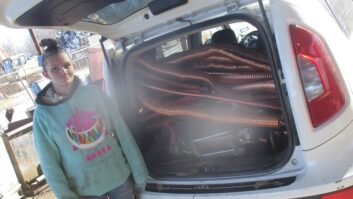
Fig. 1: Look for the obvious — in this case, a J-plug has fallen out of its jack. Greg checked the doghouses, expecting to find a roasted critter or blown capacitor, but there was neither. So he opened the phasor cabinets and found the shorting bar (J-plug) had fallen out of the J-plug jack feeding the tower in question, as shown in Fig. 1.
Over the years, the RF contactor’s constant clanging pushed the shorting bar out of its socket. That fix was quick, but Greg spent a lot more time taking pictures, tightening loose hardware — note the loose nuts lying on the cabinet floor — and checking the RF contactors. His inspection of the contactors included replacing the finger stock contact cup on one contactor that had lost half its spring fingers.
Another notable aspect of this picture is the pile of shavings on the cabinet floor under the contactor. The manufacturer’s specs for the contactor indicate that the contacts are made of beryllium copper; knowing beryllium is a carcinogen, Greg did not simply sweep or vacuum up the shavings. Instead, he hosed down the area with Formula 409, wiped up the wet shavings and disposed of it all in a bag.
Later, Greg also used 409 and a Scotch-Brite pad on the meter jack ceramic insulators in the picture. This station had a studio fire in the ’70s, and the soot from the burned Fidelipac 300 carts still covered the inside of the phasor components … a mess that will have to be completed in the months ahead. Keep in mind that insulators aren’t efficient when they are covered with grime.
Greg, this is a great maintenance plan.
Workbench readers, keep snapping those pictures. You dramatically reduce your liability by photo-documenting the condition of things before you start working on them, especially if you are a contract engineer. Don’t let it be your word against someone else’s. Back it up with photos.
Have you experienced a situation in which photos saved your hide? Drop me a line and tell me about it: [email protected]. And include a high-resolution photo, too.
* * *
Consulting Engineer Tim Sawyer posted a comment to the online version of the July 4 Workbench, regarding what’s lurking inside electrical boxes. Tim writes that it’s not just heated components inside the electrical box that the engineer needs to worry about.
As suggested in that column, Tim has often used a “spot infrared thermometer” with a spot/distance ratio of 1:8 or better (8-inch distance = 1-inch spot) elsewhere at the transmitter site.
Both Tim and Cris Alexander, Crawford Broadcasting’s director of engineering and a Radio World contributor, have found these infrared thermometers great for checking tuning coils and other RF components for overheating in a phasor or tuning unit. It would have been interesting to see the heat generated in Greg Richwine’s experience of burnt RF contactor finger stock.
Another consideration is that the high RF field interferes with the readings. If you have found one of these thermometers that works well in a high RF field, let us know. Otherwise, Tim writes, simply try it and take it back if it doesn’t work.
RFI immunity is important, but equally important is the spot distance ratio. You want to be able to zero in on the overheated component.
If you have one of these thermometers and RFI is a problem, all is not lost. Stand at the ready to measure the components as soon as the transmitter is turned off. If things are overheating, it will take a few minutes for them to cool, so problem areas should be obvious.
In addition to “looking” at the temperature of coils and capacitors, be sure to check the nuts and bolts that join junctions of tubing to the components. Every junction and component should be checked for tightness.
Cris makes it a point to check coil clips and rollers on variable coils too. Many times, mica transmitting capacitors fail after developing some internal resistance between the series and shunt capacitor elements inside the package. This often produces a steady or intermittent parameter shift that can be tough to track down.
Resistance, in the presence of significant current, produces heat, so an IR thermometer often will disclose a failing capacitor. In an AM tuning network, the one cap that’s considerably warmer than the rest is suspect and should be investigated.
Then there are the FM RF elbows, and anywhere there’s a bullet in a rigid line system. Tim has had tower crews climb with one of these IR thermometers, mapping out each 20-foot section of rigid line. You’ll find these little gizmos are invaluable to reliable operation of an RF plant.
Contribute to Workbench. You’ll help your fellow engineers and qualify for SBE recertification credit. Send Workbench tips to [email protected]. Fax to (603) 472-4944.
John Bisset has spent 43 years in the broadcasting industry, and is still learning. He is SBE certified and is a past recipient of the SBE’s Educator of the Year Award. He recently joined Elenos USA, an FM transmitter company based in Miami.