Yes, we are in the age of digital, but in my experience the vast majority of radio broadcast audio consoles still have analog audio passing through from end to end.
Have you noticed that a monaural signal, such as a microphone, often does not come out the same on left and right console VU meters?
Why is that? Well, console repairs (and accidentally bumping a calibration control) can easily cause a noticeable imbalance between audio channels. It is especially noticeable in automobiles, where passengers are fixed in location and will hear a disparity in left/right levels. Listeners especially hear it when changing from one station to another. Console miscalibration can also result in annoying audio distortion.
However, you may have done nothing to create this situation.
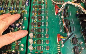
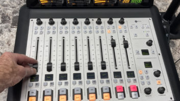
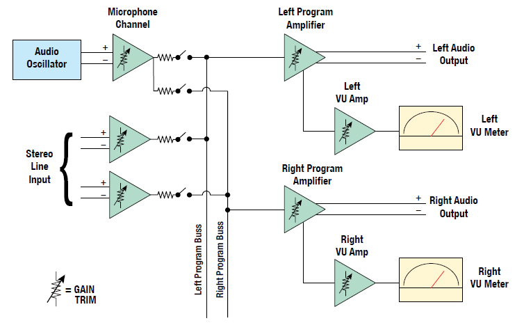
Fig. 2 shows the inside of a typical audio console. It might have been a sneaky/enterprising board operator who decided he or she could make things better by adjusting the internal controls. (Shame!) The good part is these problems are easy to fix … except for the announcer/board operator.
Remember the oscilloscope I talked about in an article titled “Your Scope Is a Tool for All Seasons” (RW Jan. 16, 2013)? Well, you need an oscilloscope to do this work.
An audio oscillator is the other tool required for this exercise. The best sine wave oscillator I’ve found is the Potomac Instruments AG-51 Audio Generator. It was designed in the days when stations were required to do annual audio proof of performance measurements to keep the Federal Communications Commission happy.
LET’S GET GOING
When beginning console calibration from scratch, I first attempt to get manufacturer’s instructions on what levels to run. Lacking that, I set the audio generator to have -50 dBm output into 150 ohms and run it to a microphone channel at a frequency of 1 kHz. All other channel controls are set to zero while the microphone control is set to the normal point, which is typically half or two-thirds of the way up.
Ideally, the left and right VU meters will read 100% (0 dB), about three-quarters scale, at that point. Chances are they will not. There might be one or two gain trim controls on that channel to tweak gain to get close to 100%. A single control that runs left and right gains up simultaneously is easy. That means left and right audio should leave the microphone channel at equal level. The goal is to have identical audio on the program and audition mix busses. Stereo line input channels often have individual left and right gain trims, but you can deal with that when tweaking gain for each source in a studio situation.
YOU CAN DO THIS
This is a good time to look at frequency response. A failing electrolytic coupling capacitor could be limiting the low frequency response, causing the station sound “tinny.” Audio proofs of the past uncovered these problems that might have otherwise gone largely unnoticed.
Change the oscillator frequency to 100 Hz, then 10 kHz. The meters should stay within 1 dB. If not, look in the manufacturer’s specifications to see what is normal. Today’s console designs have flat frequency response from 20 Hz to 20 kHz or more.
Advance the audio generator output to 20 dB above that point. Both VU meters should be pinned to the right. Not to worry because they will live through the experience. After all, announcers typically do that many times on a shift! (As a side note, we engineers need to educate operators to watch VU meters and set levels to peak at 100% for best audio consistency, not to what sounds best to their ears.)
Connect an oscilloscope to an audio output on the console. Oscilloscopes typically are unbalanced devices, so attach the scope’s probe ground to console ground. Put the probe tip on one audio output terminal of the console. That assumes the console has active balanced outputs and does not have a transformer output. It’s best to disconnect any wires attached to the output terminals so the circuit is not loaded in any way. If there is a transformer output, use a 600 ohm/half-watt resistor to terminate the transformer for best frequency response. In that case, the oscilloscope’s probe ground can go to one side of the transformer and the probe tip to the other.
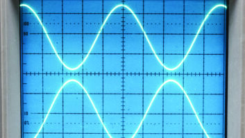
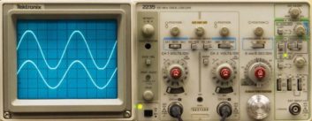
You should be at or near the point of clipping the audio sine wave about now. Adjust oscillator level up or down a bit. If you are using a dual trace oscilloscope with two probes, you can view left channel on one scope trace and right channel on the other. Fig. 3 shows a level disparity between two channels.
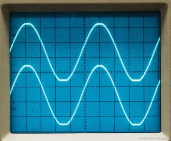
Adjust console program amplifier master gains so the left and right channels just start to go into peak clipping (flat topping) at the same time as in Fig. 4. Then reduce oscillator level by 20 dB. The VU meters should be at about 100% (0 dB). If not, adjust VU meter calibrate controls to get the meters to that point.
SUCCESS
Now you have 20 dB of headroom above normal level before clipping starts. That is a good place to be because the noise floor of the audio should be 60 dB or more below that point, which is the specification for FM broadcasting. It is 45 dB for AM broadcasting, but you can do better than that nowadays. This 100% audio level is a balance between clean audio without clipping, down to residual noise. You are fighting both ends of the audio dynamic range at this point. Do the same for the audition and any other busses.
I built WDCQ, now WJUA, in Pine Island Center/Fort Meyers, Fla., back in 1986. It was at the peak of the AM stereo days so I modified the main studio audio console to provide “gain tilt” for on-air microphones. All was normal when only one of the two microphones was turned on.
The left/right gain of the two microphone channels changed whenever the second mic was on. The main announcer was full volume on left channel, but was 6 dB low on right channel. The opposite was true for the second microphone.
When listening in a car to the two-headed morning show, the listener would hear the main announcer on the left and his sidekick on the right. It was an interesting effect that brought good comments. But the CRL audio processing provided a fair amount of monaural gain support, so monaural listeners hardly heard a volume difference.
This article is your recipe to ensure clean and balanced audio.
Mark Persons, WØMH, is a Certified Professional Broadcast Engineer and has more than 30 years’ experience. His website is www.mwpersons.com.
Comment on this or any article. Write to [email protected].