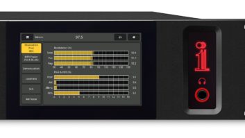
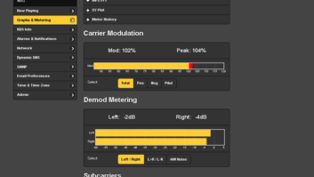
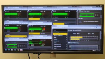
The author is CEO of manufacturer Belar Electronics.
The modulation monitor has a reputation as an obscure component in the RF chain, and there is truth behind the statement.
For decades, engineers generally installed the box and left it alone, revisiting it for an occasional cursory glance at the front panel, along with the odd troubleshooting need around signal performance.
However, the rise and proliferation of digital media and technology in the air chain have breathed new life into how the modulation monitor can bring value to RF performance. Stations are mixing analog and digital information into the same channel streams, creating new challenges in signal separation. HD Radio technology itself brings new challenges and requirements for both compliance and performance.
As modulation monitors become more software-defined and IP-connected, both vendors and broadcast engineers are able to address these emerging needs more easily. In this article, we’ll address the various emerging challenges in the RF air chain, and how the modulation monitor is evolving and adapting to these needs for the benefit of the broadcaster.
ANALOG AND DIGITAL SEPARATION
The separation of analog and digital signals at the modulation monitor quickly is becoming a common application.
Hybrid analog/digital signals containing HD Radio carriers gradually have been introduced into the RF chain. Broadcasters quickly recognized that a significant amount of self-interference was introduced into the total modulation measurement as a result.
That interference raises the modulation levels, which makes it difficult to attain an accurate total measurement in the presence of HD Radio carriers. This often forces broadcasters periodically to turn off HD Radio carriers to achieve an accurate total measurement; or, in the presence of high-level combined system that combines separate analog and HD Radio transmitter signals into a single antenna, assign analog monitors to the analog transmitter. The latter option enables the broadcaster to generate a total analog reading without an HD Radio presence.
However, there are significant detriments to both of these approaches. Shutting down the HD Radio carrier also kills the on-air audio and data, alienating the already scant HD Radio listening audience. The second option works well in theory, but is useful for only a minority of broadcasters since far more systems are low-level combined.
Low-level system configurations can natively produce both an HD Radio and analog signal presence in the same stream, making it possible for broadcasters to separate the two signals inside the mod monitor. This brings the benefit of recovering accurate total readings in the presence of the HD Radio carriers.
This process has become much more difficult with the FCC-approved increase in HD Radio sideband power to a maximum of –10 dB. Noise and interference in the total measurement rise as the HD Radio carrier power is raised.
The evolution to a more software-defined architecture for the modulation monitors has built a foundation for incremental enhancements, including filtering and peak weighting, which improves total measurement accuracy. This is significant because there are few positions in the air chain to successfully apply filtering. The first strategy is to apply filtering on the actual RF spectrum, before being fed into the FM demodulator. This application adds a bandpass filter, which passes roughly plus or minus 100 kHz. That process suppresses the HD Radio sidebands so that the FM demodulator sees only the analog signal.
The downside is that distortion is created while band-limiting the FM signal, which causes errors in the measurement. However, those errors are usually far less significant to the total measurement compared to the HD Radio sideband-influenced modulation increases.
The second filtering point follows the FM demodulator, where the composite baseband signal exists. It is possible to band-limit the signal at this stage. In a typical analog configuration, the signal may contain SCA subcarriers, requiring a minimum 100 kHz bandwidth. Upon removing the SCA subcarriers from the air chain — which is increasingly more common — the bandwidth of the composite filter can be significantly reduced. This is achieved by bringing the 100 kHz bandwidth down to 57 kHz, which allows for passing only the RDS subcarrier. With everything but the RDS eliminated, the broadcaster wipes out as much as 50 kHz from the spectrum, along with a significant amount of noise — thus, lowering the total measurement.
An example that demonstrates how self-interference affects total readings at HD carrier power levels of –10 dB, –14 dB and –20 dB using the Belar FMCS-1 with its variable RF and composite filtering is in Table 1.

Table 1: Analog Test Signal: 1 kHz L+R @ 90% with 9% pilot
A third possibility is to apply a peak weighting algorithm on the total measurement after the RF and composite filtering. This further reduces the total measurements by eliminating some of the higher-frequency peaks. By removing those peaks, the broadcaster can bring down the total modulation. This is especially useful when monitoring signals off-the air.
Broadcasters with a sizeable noise floor can remove most of these undesirable artifacts from the HD Radio signal through an intelligent and thorough filtering strategy. By building composite filtering and peak weighting algorithms into the mod monitor, broadcast engineers more easily can make measurements in the presence of HD Radio carriers at higher power levels.
EFFECTIVE POWER MEASUREMENT
The FCC’s power level increase approvals over the years (–20 dB to –14 dB, and subsequently, –10 dB) have magnified the need to effectively measure HD Radio power levels for compliance. The FCC mandates a defined ratio between analog FM signal power and HD Radio carrier sidebands.
Spectrum analyzers have traditionally been used for power ratio measurements, which communicate the power vs. frequency relationship of hybrid RF signals. In addition, the FCC and NRSC have specified an RF frequency mask for RF emission compliance. (For a fuller discussion of the measurement techniques, RF mask compliance and HD Radio carrier sideband power, refer to NRSC-G201-A and G202 documents.)
Sometimes, when HD Radio sideband power elevates interference to unacceptable levels, the RF mask needs to be adjusted based on the different upper and lower sideband power. This encompasses asymmetrical distribution. For example, the upper side band may be at maximum power while the lower sideband may be at a reduced power. This would result in an RF mask limit of –30 dB on the upper sideband and –34.0 dB on the lower sideband, with a –4 dB reduction.
Because of the many possibilities of how carriers can now broadcast, it is more important than ever to better define measurement strategies to verify that levels are correct and unchanging. The approach to accurate measurements will be somewhat different depending on how your signals combine in the RF system.
In low-level systems, as stated above the analog and HD signals exit the transmitter fully combined. As a result, the analog and HD carrier power ratio is set and determined in the exciter. Accurate samples may be taken at the transmitter in these instances.
High-level combined systems feature two transmitters. There are variations to high-level combining — one delivers HD Radio and analog signals from each transmitter — but the traditional approach utilizes separate analog and HD Radio transmitters, each broadcasting separate carriers. The combining of the signals takes place later in the RF process, but the HD Radio and analog signals come together prior to reaching the antenna.
Space-combined or antenna-combined systems represent the greatest challenge. Like high-level combining, this approach uses separate analog and HD transmitters. The difference is that the paths run entirely separate through to the antenna. Because these signals are not combined prior to the antenna input, the only means of attaining an accurate power measurement is off the air.
To ensure the signals are combining correctly, the broadcaster must calculate the losses of both the analog and digital paths and then adjust the transmitter and sideband power. This formula will verify that the power ratio is correct based on the analog and digital path calculations.
Traditionally, broadcasters have required a dedicated spectrum analyzer for accurate mask compliance measurements. These gradually have come down in price in recent years but can still be an uncomfortable expense for most radio stations.
In contrast, the modern modulation monitor has the ability to simplify measurements greatly across all these options, particularly in the area of antenna-combined systems. However, to cover all possible HD Radio implementations, the measurement device must have two internally combined high-level RF inputs and/or a separate antenna input.
The ability to measure spectral mask in the same workflow provides an additional benefit. The spectral mask laid atop the RF spectrum ultimately determines if the station is in FCC compliance. That mask changes based on the broadcaster’s upper and lower sideband power. Belar recently has integrated software to continuously measure the analog, upper HD Radio sideband and lower HD Radio sideband power. Using these measurements, the ratio between analog and HD Radio power is calculated and subsequently displayed in real-time.
Modulation monitors with an adjustable mask can address mask differences on asymmetrical sidebands without requiring an external analyzer for spectrum measurement. The mask can be adjusted to run higher on one side and lower on the other, and be set in alignment with the transmitting power. By laying the mask atop the spectrum inside the mod monitor, the broadcaster can confirm visually that the station is both in mask compliance and transmitting the appropriate sideband power.
Broadcasters interested in measurement of both power ratios and mask compliance within the modulation monitor should first confirm that the unit will provide the actual measurements. In addition, since the most accurate measurements are attained at the transmitter site, having a monitor with a remote interface is to the broadcaster’s benefit.
Moving forward, enhanced IP networking within the RF chain should open additional doors to further advances. One possibility is feeding both power and mask measurements back to the exciter — similar to Belar’s HD diversity delay measurement process — so that the exciter comprehends what is happening in the field. This is just one possibility on the horizon to emphasize how the modulation monitor can bring greater efficiency to problem solving in the RF chain.

Fig. 1: The time alignment screen shows current device delay and calculated delay correction to be applied.

Fig. 2: Graph shows a delay correction applied to the audio processor by the Belar FMHD-1.THE CHALLENGE OF DIVERSITY DELAY
Speaking of diversity delay, there is no question this is today’s hottest HD Radio topic not only for mod monitors but for HD Radio in general.
The roughly eight-second delay between the analog and digital signal has long been a headache for engineers. As the digital signal strength fades in weak reception areas — on the outer market edges, and inside tunnels, buildings and congested metro areas — that signal blends with the analog FM program.
New innovations driven by mod monitor manufacturers have started to address these challenges. Some tackle the problem directly inside the modulation monitor; Belar takes the approach of communicating changes to other key components in the air chain, where continuous corrections take place. Fig. 1 shows an FMHD-1 display of current device delay and Fig. 2 shows the delay correction applied to the audio processor as commanded by the FMHD-1.
Whether corrections are made within the modulation monitor or elsewhere in the air chain, the mod monitor must be in communication with one of three components to achieve proper time alignment between the digital and analog program. The first option is to use a separate delay line from a company like 25-Seven Systems. This was an early innovation, before manufacturers started integrating delay lines into standard HD Radio air chain components.

Fig. 3: Examples of analog-only delay correction.

Fig. 4: Examples of fixed analog delay with correction applied to the HD-1 digital signal. These delay lines are interesting as they excel in delay adjustment through compression and time-shifting, which allows the broadcaster to speed up the program without changing the pitch. Since there is no noticeable difference to listeners, broadcasters can actually squeeze a few more ad spots into each program hour. Separate delay lines remain the most sophisticated algorithm due to its sample-accurate time adjustments in fractions of a second; and it remains a viable option for broadcasters with older HD Radio architectures.
Companies like Omnia, Orban and Wheatstone have begun to build delay lines into their on-air processors. That built-in capability enables a direct connection to a mod monitor. In the case of Belar, our Automatic Delay Correction software connects to the processor through a network interface. Analog and digital time alignment is measured continuously, with corrections fed through that interface via a closed-loop procedure. HD Radio broadcasters can also leverage an exporter for time alignment. Companies like GatesAir and Nautel offer a built-in control protocol to communicate with the mod monitor, and continuously monitor and correct delays. Fig. 3 shows examples of how the analog audio delay can be controlled, and Fig. 4 shows how the analog audio delay remains fixed while the HD-1 audio delay is controlled.
Additionally, broadcasters applying corrections through a processor can now achieve a smoother transition between analog and digital signals. Exporters and precision delay devices incorporate a ramping function to support this, but in processors the time adjustments are often jarring for the listener.
New enhancements in diversity delay software support a gradual ramping feature that delivers a smoother transition similar to the algorithm used in exporters and separate precision delays. This makes the adjustments nearly imperceptible to the listener, eliminating the obvious time jump.
Tracking the delay error requires the calculation of a correlation function using samples from the digital and analog audio streams. The computation time of this function is dependent on the width of the time window being analyzed. At Belar, we use a variable-length time window allowing us to tailor the length of the correlation to the actual delay error. The algorithm tracks the delay and automatically adjusts the correction window if the delay creeps out of range, then contracts the window as the delay is pulled into alignment. The advantage of this approach is a faster acquisition of delay corrections, which results in a tighter overall alignment of the analog and digital audio streams.
While these three options are viable today, we see other opportunities to extend communication from the mod monitor to other air chain components — notably the transmitter. Our expectation is that this will be among the next developments in expanding the diversity delay architecture.
The integration of a scan function to correct up to six preset stations in a market is another interesting development in the past several months. This supports automatic cycling through the presets, and establishes unique IP connections to each station’s delay device. The appropriate time alignment corrections are executed once the connection is made.
This provides a benefit today for stations that are monitoring multiple stations on different frequencies. Hubbard Broadcasting, for example, is using two separate inputs to service two different RF feeds, frequencies and delay devices for scanning two stations, KMQV(FM) and KRWM(FM),
The greater emergence of single-frequency networks has added a new wrinkle to the fold. These networks are becoming more common as a means to enhance coverage in challenging locations, such as mountainous terrains and congested metropolitan areas.
To achieve greater coverage, these networks use multiple transmitters — typically lower power — and lock the transmitters together over a single frequency. This is similar to how a cellular phone network works. The radio broadcaster operating a single-frequency network or SFN adds strategically positioned boosters and repeaters to strengthen coverage across that network.
The challenge: How does the broadcaster keep costs low and processes manageable when delivering HD Radio over such a complex network? The traditional model of a standalone transmitter with an exporter and processor for each location quickly adds up in an SFN configuration. Instead, engineers are architecting these networks to support multiple transmitter sites from a single exporter, with signals fed over multipoint IP networks.
As more networks like this are deployed, the need to develop a diversity delay within the transmitter grows in importance. Since there is no need to duplicate each transmitter site with dedicated exporters and/or expensive standalone processors, enabling corrections inside the transmitter represents one viable solution. The multi-scan function mentioned previously could be applied in this scenario, allowing one monitor to provide alignment corrections for a group of transmitters.
Perhaps the greatest benefit of a software-defined system is the ability to tweak and improve the platform continuously without significant technical overhaul, reducing the cost burden to broadcasters over time. In addition it means the ability to do more in a single box, reducing the number of components — and associated costs and complexity — in the air chain.
One thing is certain: As the need for better diversity delay solutions grows, the technology to support it will continue to evolve and mature through more software-defined innovations.
Comment on this or any story to [email protected].


