figures
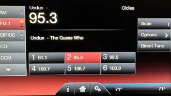
(click thumbnail)KVIV staff member Jesus Cruz in front of the CCA AM -1000D main (and only) transmitter still on the air in El Paso. credit: Courtesy Paul Gregg
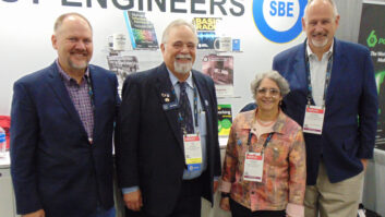
(click thumbnail)Auxiliary transmitter at WNEZ(AM), 1480 kHz in Windsor, Conn. credit: Courtesy John Ramsey In the foothills of the Rockies are high desert regions so vast that, even when viewed from 35,000 feet, they sweep from horizon to horizon. On a recent airline flight I was surprised to see in the rolling desolation below a ribbon of two-lane blacktop tracing its way to a tiny hamlet. The blacktop entered this Xanadu-like berg and ran until the paved route abruptly ended.
The unimproved road continued some distance beyond until it terminated at a communication site with one tower. As the plane flew on, I discerned the classic seven orange and white bands of a typical short AM stick. In this isolated setting, the station most likely was a Class IV (now Class C) 1,000-watt full-timer on one of the local channels.
Physically remote even today, this community must have seemed even more isolated before satellite, Internet and the other instant communications streams we now enjoy.
I reflected that this little station at one time must have been almost the center of its community, a source of news and entertainment and possibly the only commercial advertising vehicle. It combined the roles of local paper, radio station, public ledger and town crier.
CCA
Most such 1 kW stations possessed but a single transmitter. In recent Milestone columns we’ve been reviewing the ubiquitous, classic units of the tube age that worked so well for so long in such settings.
One manufacturer, Communications Corporation of America, brought its AM-1000D 1 kW to market in 1967. Like the Bauer 707 covered in Radio World last summer, its power tubes were 4-400 tetrodes. It was built like the proverbial tank, with a large, 7-1/2-square-foot footprint, compared to the more modest 6 square feet of the Bauer and Gates.
The CCA had a separate interior enclosure for just the RF output components. All of these rigs had essentially “pi” outputs networks. However, this one used adjustable coils — viewed by some as slug tuning — to tune the RF output circuit as opposed to capacitors found in most competitive rigs of the period. This precipitated a unique feature and circumstance, a coil “turn counter” that was part of the adjustment handle assembly. Two of these adorned the front and often were set to zero once the optimal tuning had been achieved. This setting made it easy to observe out-of-normal operation and to return to the original setting when need be.
The rigs had a choice of two crystals with switch selection. The Bauer and Gates normally used crystals without heaters. Some CCAs did, some didn’t; this probably was a function of customer preference.
An interesting side note is that as long as there has been an AM frequency stability standard, it has been 20 Hz (or just 20 cycles, in the Dark Ages). Why? Because an error of 20 Hz or less is below audible as far as carrier beat is concerned. If you hear a “growl” or whistle on an AM channel, the carrier difference is way more than 20 Hz. Many worried if the crystals weren’t heated that the “rocks” would not be able to reliably maintain that +/- 20 Hz spec.
Like the Bauer 707, the CCA utilized a Superior Electric Stabiline constant voltage regulator. This unit stepped down from 240 to 120 volts for input voltage to the filaments, the bias and low-voltage supplies. Three-percent regulation was achieved under severe input line voltage variations. Especially valuable was the stability of the power tube filament voltage. This feature extended the life of these bottles considerably.
Foibles
More modern regulation techniques have replaced these units in present design applications. The industry vision is that constant voltage, or ferroresonant, transformers are designed to have the core magnetically saturate at a particular voltage and frequency. As the transformer saturates, the output is limited to a relatively constant voltage. Because of the nonlinear nature of a saturating transformer, resonating components are added to prevent the output voltage from becoming too distorted. These units typically regulate the voltage to within 3 to 5 percent. However they have high impedance; they are noisy, inefficient and sensitive to frequency changes as compared to more modern alternatives.
My view is that many transmitter designers know a lot about electronics but little about electricity. In the CCA — and many contemporary units — we see another example of this.
The return path for all the 120 V control logic is through the frame of the rig. In other words, ground and neutral are the same; but as we know, they are not. Many a transmitter of this vintage has had to be rewired with a separate neutral return for the affected circuits to make it code-compliant in present tense.
Although these 1000Ds had their own foibles (like wires falling out of crimp connectors), they ran well and many still do.
One bug-a-boo was the drive sensor that would not put bias on the final tubes until the RF drive level was high enough. This drive sense circuit essentially was an RF path to ground through a relay coil and some current limiting, metering and load resistors. This was a sensible safety device that saved a lot of power tubes; but it kept many a rig off the air at the worst possible times when components in the sense path opened or failed.
I encountered a unit that had run for years in a damp pumphouse sitting next to a well. About 1,000 feet of coax ran the output up to a tower at the top of the hill (thank goodness for direct power measurement).
Another encounter was a “D” in a pathetic shed sharing its space with a bevy of mice and bugs. The pest control spray was so thick on everything that it actually changed the tuning in the transmitter and ATU.
When you were in the room with them, the 1 kW rigs of this era had their characteristic sounds; the Collins had multiple blowers, so it produced a sort of barbershop harmony sound. The CCA “D” had one big blower in the bottom of these dense rigs. Its sound was mainly the swish of much air moving.
Talking of sound: Do tube transmitters sound better? In this age of NRSC roll-off and now the HD AM 5 kHz roll-off, it’s hard to tell.
In the past, flat AM transmitters were those that reproduce audio to 100 percent modulation, +/-2 dB, from below 50 Hz to above 10 kHz, where the speakers start to roll off on the mod monitor. When A/B’ing between two such rigs it would be hard to tell from response which one was on the air. However, dynamically a tube rig does “color” the sound, especially when modulating at high levels. Soft clipping is not a figment of the imagination but a function of the surge impedance of the power transformers and the loss of peak emission as the power tubes age. In egregious cases, that coloring would identify the rig on air.
Some loved the “warm tube sound” of these rigs and miss it in the narrow band of today.
Soon we’ll look inside the Collins 20V2.