This article originally appeared in the Feb. 8, 2017, edition of Radio World Engineering Extra and was posted on this website Feb. 9, 2017. If you like this content you should subscribe to Radio World Engineering Extra.
In two articles thus far (RW Engineering Extra, Aug. 10 and Oct. 19, 2016), we’ve traced the origins of electret condenser microphones to their externally-polarized ancestor, patented in 1916.
One hundred years later, modern materials and manufacturing have made electret condenser mikes cheap and plentiful — and with careful design electret audio performance can rival the best of their powered cousins. In this chapter, we’ll examine the anatomy of the circuitry following electrets and how they affect the sound output.
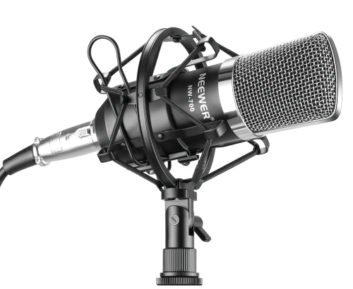
For our study, I picked a Neewer model NW-700 “Professional Studio Broadcasting & Recording Condenser Microphone,” which at the time of writing is listed at only $14.70 by the manufacturer, including a web shock mount and cable, shown in Fig. 1. Neewer was kind to let us share some of the NW-700 schematic, which we examine below.
As discussed previously, all condenser microphones generate a small voltage as their diaphragm changes capacitance in an electric field, when moved by sound pressure waves.
Externally-polarized mikes charge the diaphragm/backplate condenser through a resistor from a source of 40 to 200 volts, as shown on the left in Fig. 3.
Because the capacitance is very low (around 50 picofarad, ±30 pF), the resistor forms an R/C network that rolls off the low frequencies. The resistor must have a value of hundreds of megaohms to avoid a cutoff in the bass range.
One advantage an electret has is its intrinsic charge, which eliminates the charging resistor, as shown on in Fig. 3. Either way, a fixed charge is maintained across the capacitor.
For a charge Q, the expression is: = C0 × E0
C0 is the capsule capacitance, and E0 is the capsule capacitance.
The output voltage change of a condenser microphone is expressed as the fixed voltage times the relative change in capacity:
![\[ e_{t} =E_{0} \times \frac{c_{t}}{C_{0}} \]](https://www.radioworld.com/wp-content/ql-cache/quicklatex.com-35d2152543098e567e9b2e4119cdf9d3_l3.png "Rendered by QuickLaTeX.com")
where Ct is the variation in capacity due to sound pressure.
It is not unusual for electret microphones to have a rated output of –40 dB relative to 1 volt measured at sound pressure of 1 Pascal (Pa), which is 94 dB SPL. The signal level produced by an electret element under these conditions is calculated to be:
![\[ 10^{\left(\frac{-40}{20}\right)} =\frac{10\text{ mV}}{\text{Pa}} \]](https://www.radioworld.com/wp-content/ql-cache/quicklatex.com-049a0c20bb2f7898edf7c5b810e468eb_l3.png "Rendered by QuickLaTeX.com")
An orchestra may produce an SPL of more than 105 dB, but loud musical instruments such as horns and drums could easily produce a local SPL of 115 dB when closely miked. That is 21 dB above the reference 1 Pascal, which multiplies the output to:
![\[ 10^{\left(\frac{21\text{ dB}}{20}\right)} =11.2\times 10\text{ mV} =112\text{ mV} \]](https://www.radioworld.com/wp-content/ql-cache/quicklatex.com-92365e7bf44b2556fe58128d3b2eee28_l3.png "Rendered by QuickLaTeX.com")
This voltage is an average of the signal envelope — but the peaks of the waveform are greater. Assuming the ratio between the signal peaks and the average is 10 dB, the peak signal level could reach:
![\[ 10^{\left(\frac{10\text{ dB}}{20}\right)} =3.16\times 112\text{ mV} =354\text{ mV} \]](https://www.radioworld.com/wp-content/ql-cache/quicklatex.com-e96f714166ea33c68709c392887b9b7c_l3.png "Rendered by QuickLaTeX.com")
That is arguably a big signal for the transimpedance amplifier!
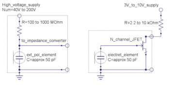
Let’s look at what may happen, beginning at the electret microphone as shown in the right diagram of Fig. 3. Nearly all electret microphone capsules have a junction-type field effect transistor (JFET) inside the case, to convert the extremely high impedance of the electret element to a useful value for the following circuitry.
Electric charges in JFETs flow through a semiconducting channel between source and drain terminals that is exclusively voltage-controlled. Unlike bipolar transistors, JFETs do not require a biasing current (although, as we will see they benefit from optimum terminal voltages). The JFET also has a potentially higher gain (transconductance) than the MOSFET, as well as lower flicker noise, making them well-suited to the microphone element’s weak signal.
CIRCUIT SIMULATION
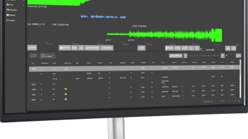
To evaluate the microphone’s transimpedance amplifier and the following stages, I used circuit simulator software. It may be a little unconventional to do this study in software rather than with test instrumentation, but this came about because I was hand-drawing the internal circuits of several microphones and the simulator allowed me to check configuration of some unlabeled parts. (In one case, it helped me determine that a transistor’s emitter and collector had to be reversed and changed from NPN to PNP.)
The simulator I chose is Qucs, the “Quite Universal Circuit Simulator,” an open-source electronics circuit simulator software available on the Internet at http://qucs.sourceforge.net under GPL. Qucs supports a large list of analog and digital components with parameter values that can be applied to circuits to study DC voltages, AC performance, including noise and transient analysis, and more.
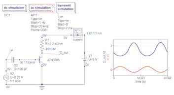
Starting with the transimpedance converter, Qucs demonstrates some powerful analysis. Fig. 4 shows the circuit with an AC voltage source in substitution for the electret condenser. Note that a 100 picofarad capacitor is placed in series to represent the element’s real capacitance. The AC has been set to a 1 kHz sine wave at 0.25 volts peak. The meter icon shows a series current of 1.6 milliamps through the 2.2 kohm resistor tied to the 2N3685 JFET drain when supplied with 5 volts.
Two test points: “in” and “D_out” are shown in the Qucs chart to the right. (This is a transient measurement with DC voltages, so the AC simulation is deactivated.) The input signal is shown in red, producing a 0.25 volt sinusoid. The output at the JFET drain is shown in blue, with some gain but also with a large distortion to the waveform. The waveform is inverted, and the negative half is distorted because the signal input voltage drove the JFET’s gate positive, and an N-channel JFET is linear only for a range signal voltages that are negative, relative to the source terminal.
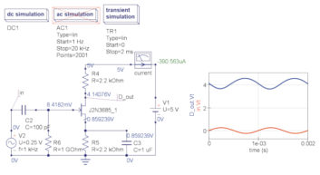
One of the simplest ways to correct the signal voltage issue is by self-biasing, that is, raising the source voltage through as series resistor to ground, as shown in Fig. 5. R5 raises the voltage at the source terminal to 0.86V in this example, while a very large 1 gigohm resistor holds the gate voltage to 8.4mV. A bypass capacitor, C3, holds the voltage on R5 steady across the audio range. (These component values are for illustration and are not optimized.)
Self-biasing lowers the JFET’s distortion, and approximately doubles the gain in this example — but at the cost of a larger component count. Considering that electret microphone capsules often must be as small as possible, as well as low in cost, designers often forego these components. This illustrates a compromise for designers, but fortunately, high acoustic levels are probably not an issue in consumer applications, such as telephones, and they may be avoided to some extent in studio recordings by microphone placement.
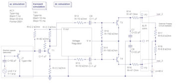
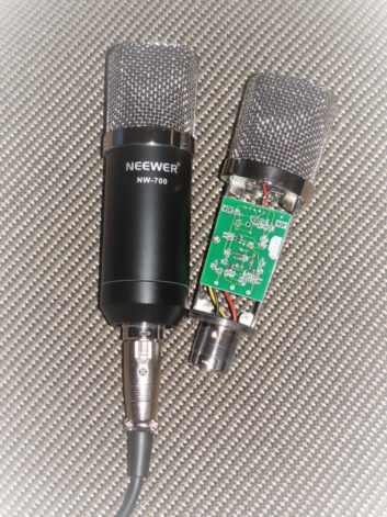
Fig. 6 shows part of the Neewer NW-700 microphone (as I traced it, less the voltage regulator section). Similar circuit designs are used in the many low-priced “studio” microphones on the market. In this case, the electret capsule’s JFET, J1, is pulled up to a regulated DC line (approximately 8.5 volts) and connected through an R/C high-pass network to a transistor stage T1, with a biphase output. This furnishes a balanced differential output for external studio preamps.
On the right, the NW-700 provides the balanced output through an XLR connector at the base of the mike. To “power” our example, a 48 volt DC battery is assumed, which is connected through resistors to Pins 2 and 3 of the XLR connector. A resistor value of 6.8k ohms is a standard value for 48 volt “phantom” systems, although many preamps supply lower voltages and may use lower resistor values.
The phantom power is connected through an R/C bypass network to a pair of emitter-follower transistors, T3 and T4, which provide approximately unity gain and have a low source impedance to the lines. The common point of the two transistors is tied to the voltage regulator, which provides the regulated and filtered DC for the input stages.
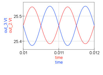
Qucs can provide a variety of AC systems analysis. In Fig. 7, a 0.1V (100mV) signal is applied through a 50 pF capacitor (simulating the assumed capacitance of a small-diaphragm electret element) to the JFET impedance converter. The output from Pins 2 and 3 of the XLR are charted as red and blue waveforms. The vertical scale is in volts, and the voltage offset, because of phantom power, runs at approximately 24.6V. In this simulation, there is slightly less output from Pin 2 than from Pin 3. However, this is unlikely to affect the noise rejection as that depends primarily on the common-mode rejection of the external preamplifier and not the normal-mode difference in signal between the lines.
IMPRESSIVE PERFORMANCE
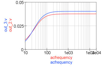
Qucs supports predicted frequency response of the system, as shown in Fig. 8. As shown by the “ac simulation” data on Fig. 6, the simulator was configured for a logarithmic sweep from 1 Hz to 20 kHz in 2001 steps. Fig. 8 shows the sweep displayed from 10 Hz to 20 kHz. The frequency response is shown on linear vertical scale in volts, so a difference between 0.25V to 0.5V is ±3 dB.
It is apparent that the response is effectively flat from 100 Hz to the top of the range, and is down approximately 3 dB at 30 Hz. Of course, this excludes the frequency response of the electret microphone, and we know from the previous part of this series [Oct. 18, 2017, issue] that directional small diaphragm capsules have an intrinsic frequency tilt that is generally uncorrectable below 100 Hz due to limitations in acoustic filter techniques. However, this rolloff is offset by proximity effect at closer distances, so pickup of voices and instruments at a foot or so is reasonably well-balanced, tonally.
Recordings made with the NW-700 are generally quite good. On symphonic recordings made on high stands, there is noticeable low-frequency rolloff, but this was easily compensated with equalization during post-recording edit. The noise level of the NW-700 is not as good as expensive microphones (those costing 10 to 100X more) but it is acceptable, even for orchestral recording.
If you are interested in a sample recording with this microphone, visit this link on SoundCloud: https://soundcloud.com/john-kean-314785812/20160213-rachmaninov-3m26s
This 3.5-minute recording was made with the Washington Metropolitan Philharmonic Orchestra at the George Washington Masonic Temple auditorium in February 2016. It was recorded with a crossed-cardioid configuration in 24-bit/48 kHz sampling and transcoded to 16-bit/44.1 kHz in Audacity, with only LF equalization. The acoustics are not ideal, as the mics had to be placed on a low stand at the front of the seating area, but the recording gives you an idea of what the NW-700 can deliver.
[Subscribe to Radio World Engineering Extra]
John Kean joined National Public Radio in 1980 after being chief engineer for a San Diego commercial FM station. In 1986 he joined Jules Cohen and Associates, and then Moffet, Larson and Johnson. He returned to NPR in 2004 to help establish NPR Labs and retired in 2015. Today he works with Cavell Mertz and Associates and performs audio consulting in private practice as Kean Consultants LLC.