One of the biggest hassles in maintaining older equipment is getting it repaired when it fails. A lot of companies don’t even want to deal with older, “legacy” equipment. Others will attempt repairs, but dwindling or discontinued parts may be an issue.
A number of contract engineers and special project/consulting engineers have picked up the slack, offering repair services.
One such repair service is Frank and Dave Hertel’s Newman-Kees RF Measurement and Engineering (contact via [email protected]).
Recently, one of their clients sent in a Broadcast Electronics FX-50 exciter for repair. The reported problem was that the exciter was producing “spurs” (spurious emissions) up and down the FM broadcast band, causing interference.
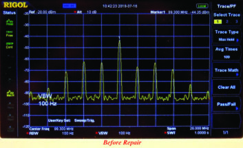
Once hooked up on the bench, Fig. 1 shows what the RF output looked like. It’s not a friendly picture — and a great invitation for an FCC visit, if allowed to continue.
Because of the precise repetition of the unwanted frequencies, Frank and his son questioned if it really was, in the pure sense of the definition, a spurious condition. The precise spacing of the unwanted frequencies pointed them to look at the frequency modulated oscillator and the filtering of the automatic frequency control voltage that is sourced from the phase locked loop.
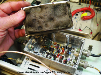
To their surprise, the AFC control voltage appeared to be free of any pulses that could be inducing the spurious problem. Next, they dismounted the Modulated Oscillator module and opened it up. Fig. 2 shows what they discovered.
[Making Sense of Component-Level Troubleshooting]
Inside the FMO module there are three electrolytic capacitors. C4 and C7 are 100 MFD @ 35 V and C6 is 10 MFD @ 35 V. The 100 MFD capacitors are used to buffer and filter the FMO modules on board regulator’s DC. The 10 MFD capacitor is used for bypass filtering of the modulated oscillator’s (Q-2) “drain” element.
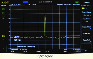
Considering the age of the exciter, and since the FMO is a sealed unit and has no ventilation, they decided to replace all of the electrolytic capacitors. They replaced the C4 and C7 — 100 MFD @ 35 volts capacitors with 330 MFD @ 35 volts capacitors. The C6 — 10 MFD @ 35 volts capacitor was also replaced with a new 10 MFD @ 35 volts capacitor. The deteriorated foam was removed from the lid and the residue cleaned away and blown off all of the internal parts. Fig. 3 shows the RF output as a result of the repairs.
After the successful repairs, they measured the values of the removed electrolytic capacitors. The C4 and C7 (100 @ 35 volts) capacitors checked good in their value, but exhibited a slightly elevated equivalent series resistance.
The C6 (10 MFD @ 35 volts) capacitor was only slightly lower than its rated value, but its ESR value was elevated. An elevated ESR, in an electrolytic capacitor, will tend to make them become slightly inductive, and thus, they become resonant and can “ring” at some frequencies.
The rated value of a capacitor can be misleading when working with RF circuits. Frank writes that it is wise to check the ESR value of any capacitor that is used in an RF (or any) circuit. If you do not have an ESR capacitor tester, play it safe and replace the electrolytic capacitors.
[Replace Electrolytic Capacitors — Before They Explode!]
Keep in mind that electrolytic capacitors are rated in temperature range and projected hours of use. Research and use only the “best” rated electrolytic capacitors. This is not a place to cut corners.
In recent columns, we have discussed the need to replace electrolytic capacitors about every seven years. If you have older equipment with the original electrolytics inside, your best preventive maintenance is to shotgun (replace) them all.
If you’re troubleshooting older gear with the original electrolytics, a lot of time can be saved by first viewing the power supply voltages on an oscilloscope for excessive ripple on the DC power supply rails.
The list of problems that bad electrolytics can cause is a long one. Save yourself the headache by getting rid of these ticking time bombs!
***
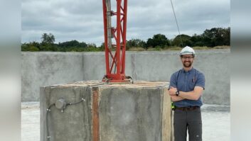
Dan Slentz found another interesting product on Amazon. It’s an $8,000 tiny home that can be constructed in just eight hours. Manufactured by Allwood, the structure cannot be used as a house, as there is no kitchen or bathroom, but a permanent structure for a remote broadcast studio at a fair or similar location is certainly a possible use case.
Here’s the link for more information.
Contribute to Workbench. You’ll help fellow engineers and qualify for SBE recertification credit. Send Workbench tips and high-resolution photos to [email protected].
Author John Bisset has spent 50 years in the broadcasting industry and is still learning. He handles western U.S. radio sales for the Telos Alliance. He holds CPBE status with the SBE and is a past recipient of the SBE’s Educator of the Year Award.