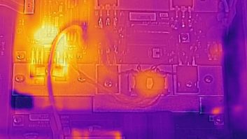
(click thumbnail)Fig. 1: A gang of high-voltage bleeder resistors.Last issue I encouraged you to inspect and clean transmitter capacitors. Through an inspection with a bright trouble lamp, you can spot potential problems like leaks, bulges or heat-discolored terminals that indicate pending capacitor failure.
Another component that you’ll find in large tube-powered transmitters could save your life. Wire-wound resistors are used throughout these big rigs. Several usually are ganged together to provide a discharge path for the high voltage when the transmitter is turned off. If the resistors open up, or their contacts are corroded, your safety is in jeopardy. Visual inspection of these resistors usually can identify a problem.
Here’s a slick trick that can spot trouble before you even open the transmitter door: Turn the transmitter plate supply off while watching the plate voltage meter. The meter should quickly drop down to zero as the voltage bleeds to ground through the string of resistors, as seen in Fig. 1. If the meter hangs up near the typical plate voltage reading even after the plate has been turned off, or if it drops very slowly, you’ve probably got bleeder resistor problems.
What you are seeing on the meter is plate voltage with no place to go; or if it has to bleed through corroded resistors, it may take awhile. In either case, high voltage can be present on components after the transmitter power is off. Of course, if you open the transmitter door before the charge has bled off, the High Voltage Interlocks should quickly discharge the voltage – providing a loud crack, a reminder of how easily you could be killed coming in contact with the lethal forces.
With your bright trouble light, inspect the connections of this string of resistors. Fig. 2 shows these resistors mounted with a bolt-secured bracket. Some are mounted with spring contact clips. After verifying that all components have been discharged with the grounding stick, check the terminals, wiring and connections.
Older bleeders may have a green corrosion between their contact band and bracket. Remove the resistor and clean the contact band and bracket with isopropyl alcohol. In the case of spring clips, ensure that the clips are tight and making good contact.
In addition to the visual inspection, use a VOM to test continuity. Older wire-wound resistors sometimes develop a chalky “open” where the wire actually opens up and forms a white chalk crust at the break point. The resistor outer coating should be smooth, with no surface imperfections. Investigate any abnormality.
Keep these resistors clean and working; the practice will help keep you safe. It only takes a few moments; do it at least several times a year.
* * *
Frank Grassi has worked as a recording engineer and videographer in Brooklyn, N.Y., for over 30 years. His assignments in videotaping have required taking note of sound systems used in pre-World War II buildings.
(click thumbnail)Fig. 2: Keep bleeder connections clean and tight.
The cable found by Wes Boyd of Cumulus, which we showed to great interest in our Aug. 17, 2005, edition of Workbench, is familiar to Frank as a “school” cable.
As others pointed out, older public schools used the “polarized” three-pin plug to “twist lock” microphones into an auditorium’s P.A. system stage box. The twisting action, and the fact that one prong was larger than the others, ensured that some heavy-handed custodian or teacher couldn’t accidentally remove the connection from mic to amp.
The “RCA plug” on the other end looked like the usual “prosumer” interface; Frank surmises if you unwrap that electrical tape, you will find a resistor or two used to pad down the output from an audio mixer, phono preamp or some other line-level device to match the microphone level input of the house system.
It is a “lazy way” to feed signals into the amp without crawling behind some dusty old rack to find the “Line In” jacks that usually were occupied by a separate FM tuner or a phonograph. Thanks, Frank, for the first-hand experience.
Readers might also be interested to learn that after a long career working for himself in audio and video, Frank accepted a position as a subway car inspector on the midnight shift for New York City Transit.
He now works on computerized “new tech” cars from Bombardier and Kawasaki. His electronics background was good enough to land the job at age 58. He’s been on the job for four years and is considered a top troubleshooter on these $2 million cars.
For those who think they can’t do anything else but radio, consider this: Frank didn’t even know computers when he began the job.
Frank adds that he’s learned a lot from Workbench columns about maintenance shortcuts and tricks to make his audio, video and computer careers fun and challenging. Frank, we’re glad to have contributed along the way.
* * *
Wes Boyd – who contributed the “dead man’s cable” photo Frank mentioned -sometimes needs an OIB, the brand of operating impedance bridge manufactured by Delta Electronics, but couldn’t get his hands on one. Don’t expect to find one in the used equipment pages; once someone buys an OIB, they usually hold onto it for life.
About six months ago, Wes found the Autek VA1 RX Vector Analyst, a great, inexpensive impedance measuring device. Although not an OIB, this device works in a pinch. It tunes below 500 kHz and up past 30 MHz (in several bands).
(click thumbnail)Fig. 3: The Autek VA1 helps determine impedances.
This little tester shows a frequency display, with course and fine tuning, of the internal oscillator, which will check SWR across those frequency ranges. It also performs measurements like an OIB. The Autek VA-1 is a 9V, shirt-pocket device that costs $200.
Unlike the OIB, this is not an operating impedance bridge, but Wes has used its internal generator to rough-tune the temporary antenna for WPIC(AM) at 790 kHz, as well as loan it out to tune an STA antenna on WGRP(AM) at 940 in Greenville, Pa.
Wes made the mistake of checking his HAM “tri-bander” and found he needs to take the antenna down and retune it. His only complaint is that the power switch is a little pushbutton, which can be left on by mistake and drain the battery in a few days.
Wes has seen the company set up at the Dayton Hamfest, but if you can’t wait for that, get more information from the company’s site at www.autekresearch.com/va1.htm