In this era of consolidation, things are done a little differently.
Instead of one satellite receiver, there may be several, each feeding the same or different stations with specialized programming. One of the challenges of today’s broadcast engineer is to control multiple-station automation systems with a single relay on the back of a StarGuide II or III receiver. If you parallel all the automation systems across the single StarGuide relay, events will be fired on all the stations, even if you aren’t running that specific satellite event on all the stations.
This was the problem facing Jeff Caudell, market engineer for Clear Channel’s Harrisonburg, Va., cluster. Simply put, Jeff needed a way to provide isolated multiple pairs of contacts for each automation system.
One certainly can buy a box that will tackle the problem. But in rummaging through his parts drawers, Jeff found a bag full of SK2086 dual transistor opto-isolator chips. A quick trip to Radio Shack provided a couple of proto-boards, and the construction began.
Jeff’s plan was to provide four contact pairs for each relay contact pair on the StarGuide. Because the SK2086 provided two opto-isolators per chip, each of the four input LEDs are paralleled together and tied to the relay contact pair on the StarGuide. A single 100-ohm current limiting resistor was calculated.
This calculation isn’t difficult. Look at the voltage drop across the LED and use the resistor to limit the current. You’ll need the nominal current to light the LED for the supply voltage used. Then calculate the current through resistor “x” to drop the remainder of the supply voltage. (Esupply – Ediode drop = Eresistor drop, where E is the voltage.)
To get the resistor value, divide the Eresistor drop by the nominal diode current. When making this calculation, though, remember that you are lighting four diodes, so the total current is four times the nominal calculated value.
Once you have the resistor value from the above formula, use I²R=Power to determine the proper resistor wattage. Jeff experimented with the current limiting resistor, and though the nominal current was 10 mA, he chose 7.5 mA. The lower current draw keeps the size of the wall-wart powering the circuit small.
On the control side of the opto-isolator, tie the emitters to the ground for each system, and connect each of the collectors to the command line for the respective station. The emitter grounds only come live when that particular source is on, so unless that source is selected by the automation system, it won’t fire.
Another way to explain the operation of the circuit is that two events must occur for the automation to fire. First, the automation must switch the ground “on,” and then the relay closure must occur to fire the event. By isolating each automation system, multiple firing is eliminated.
Jeff’s circuit could be revised to use multiple relays, but keep in mind, he used parts already on hand; and relays are usually much more expensive than opto-isolator chips. The big saving here is the project was completed with parts on hand.
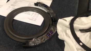
The chassis was from an old Broadcast Tools device. Jeff chose the perf-board and the proto-boards to make assembly and troubleshooting easier. The chassis rack has enough room for a second control board if it’s needed in the future. The screw-spacers that keep the boards spaced above the chassis are from subminiature D-connector plugs — again, something on hand in the parts drawer.
. . .
Planning for emergencies is something we don’t like to think about, but with a little care, a lot of confusion can be alleviated.
I saw an emergency vendor contact list that was pretty thorough. It was posted at a CVS Pharmacy! In addition to the building address, phone and fax numbers (for relating to police), the list included such things as the electric utility company (for power failures), the HVAC contractor, the telephone company and the plumbing contractor.
The list also included vendors such as locksmiths, glass companies, security, other utilities and even the cleaning company. Granted, the air staff doesn’t need all these numbers; but in an emergency, you might. If you’re on vacation or cannot be reached, posting this information in your office might help your assistant or fill-in get the problem solved quicker.
It’s helpful to include the utility account numbers as well as the telephone numbers. Some utilities won’t dispatch service personnel until they can identify the property. In the case of transmitter sites, and sites that have changed owners — and call letters — it can take some time to figure out the account.
On a weekend or in the middle of the night, the business manager may not be readily available. These are the times the planning for emergencies will make you shine.
. . .
Got a rodent or insect problem around your transmitter site?
Tim Parker spearheaded an effort at Bonneville’s WWZZ(FM) in Washington to rid the transmitter building of weeds, grass and brush.
A layer of crushed gravel around the perimeter of the building prevents all but the most tenacious weeds from growing. No brush, no cover for the pests. The pest problem dropped to zero.
Submissions for this column are encouraged, and qualify for SBE recertification credit. Fax your submission to (703) 323-8044, or send e-mail to [email protected].