(click thumbnail)Despite a discouraging first impression, I decided there was hope for this ITA FM-250B.I’m always on the lookout for interesting electronics restoration projects. Fire and flood damage is not a problem, and the older the equipment, the better.
When the faculty advisor for WDCV at Dickinson College mentioned that their 1960s-vintage ITA 250-watt transmitter probably would never operate again, I asked to see for myself.
I remembered this transmitter when it was at the local commercial station where I hung out in my high school days. The ITA went into service when the station signed on in 1963. It had been used by WDCV for a few years, but had not operated since the early 1980s.
The 250B had definitely seen its share of abuse since I’d visited it last. Dirt, cold solder joints, bogus modifications and missing hardware seemed to be the order of the day.
It would be a challenge, but I could definitely see it working again. Two hallmarks of ITA transmitters are massively-overrated components and simple circuitry. Any parts I would need are readily available from shops like Fair Radio Sales or Surplus Sales.com.
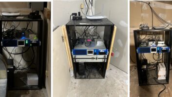
The first step was to document everything with a digital camera. This is not just for impressive before and after photos, but as an aid in disassembly. It is a lot quicker than making detailed sketches before taking everything apart.
(click thumbnail)A mysterious ‘flying wing’ was removed from the low-pass filter of the ITA.
After searching the transmitter room, I was able to find all the pages of the instruction manual, including readings taken at the time of installation in July of 1963. Unfortunately, the large overall schematic was missing. Following an appeal on the Net, I received a scanned copy via e-mail.
A sign of life
The only way to begin a project like this is from the top down, working with a paint brush and shop vac. Using dentist’s tweezers and needle nose pliers, I carefully extracted all the hardware from the crevices in the bottom of the transmitter before giving it a thorough vacuuming. I cleaned the outside with warm water and a liberal amount of Spray Nine. Soon I was able to discern the original color and was able to work on the transmitter without having my hands turn black.
(click thumbnail)After replacing broken meter glass and a through cleaning, it is starting to look respectable.All of the transmitter’s silver-plated N connectors had turned dark with tarnish and grime years ago, and sections of RG-8 coax had the consistency of a coat hanger. As I progressed through the 250B, all were removed, cleaned and lubricated with DeoxIt. I replaced old coax with new and confirmed continuity with an ohmmeter.
The Serrasoid exciter that was part of the 250B was a project unto itself. After removing it from the transmitter, cleaning and testing tubes, I disassembled it fully and checked all resistors and capacitors individually. About a third had to be replaced.
Now the inside of the exciter looked great, but it would not tune up properly. Some mystery components and unresolved issues remained.
Sleuthing around yielded some good contacts for help. Arno Mayer, president of Belar Electronics Lab and designer of the ITA exciter, had vivid recall of some of its quirks. Steve Hemphill of Belar had already restored an ITA; he provided many useful suggestions.
(click thumbnail)About one-third of the resistors and capacitors had to be replaced in the exciter.
Soon the exciter came back to life with the expected 10 watts output.
(click thumbnail)All the components on the PA cabinet were removed and cleaned. Silver-plated parts were polished with Tarn-X.
Tedious job
I placed a 50-ohm, 3 dB pad between the exciter output and PA input. One of the undocumented quirks of these FM transmitters was that most of the lower power units did not require the full 10 watts drive. In the case of the 4CX250B, 3 watts is about all that is needed.
Since there is no way to reduce the power of the exciter, a home-brew pad is necessary. This not only delivers optimal drive to the PA tube, but provides better matching for the exciter output.
Tarnish and grime ruled the inside of the PA enclosure too. At some point the threaded rods for the sliding connectors had been lubricated with 3-in-1 oil, which had coagulated with heat until the controls would barely turn. The screw that secured the plate cap on the 4CX250B had been cross-threaded, overtightened and broken off, leaving a tedious job with vice grips and a tap to remove the stub and re-establish the threads.
(click thumbnail)After the parts were cleaned, the ‘before’ photo was used as a guide to get everything back together correctly.Cold solder joints and solder blobs were all that secured wires to the PA tube socket. Brass hardware, which is always used for RF components because it does not radiate, had over the years been randomly replaced with zinc and stainless steel.
I removed everything from the PA cabinet and gave it a bath in the kitchen sink. Silver-plated parts were cleaned with Tarn-X before reassembly. The PA tube socket was gently scrubbed with a toothbrush, and excess solder was removed from the pins.
Serrasoid ModulationOne of the earliest techniques for developing an FM signal was Serrasoid frequency modulation. The circuitry was a form of indirect FM, and was used by virtually all transmitter manufacturers except RCA and Western Electric, who pioneered direct FM.
Designed by James R. Day of REL (Radio Engineering Laboratories), Serrasoid modulation was first described by Day in the October 1948 issue of Electronics magazine. His article included an endorsement by Major Edwin Armstrong, who stated, “I have always felt that phase-shift FM would be the surviving method.”
(click thumbnail)This CCA FM-10DT served as the original WDCV(FM) transmitter and is now a backup. It is fully operational.Serrasoid’s popularity began to wane in the mid to late 1960s, as stations began to convert to FM stereo. Stereo generators were available for Serrasoid exciters, but separation averaged around 40 dB, not too impressive. Newer solid-state designs utilizing direct FM were introduced which provided better stereo specs, including separation approaching, and ultimately exceeding 60 dB.
Serrasoid FM enjoyed a resurgence of popularity in the 1970s, as many equipment manufacturers repackaged their older tube-type exciters as 10-watt transmitters for the burgeoning Class D FM market.
One of the hallmarks of the circuit is outstanding sonics. The ITA FM-10 for example, boasted distortion below 0.25 percent from 100 – 15,000 Hz. In stereo mode, the response was down less than 0.2 dB at 15 kHz, and less than 3 dB down at 25 kHz. Not bad for 1950s vacuum tube technology.The squirrel-cage blower for the PA was disassembled and bathed as well. I used a wire brush to get dirt out of the concave surfaces of the fan blades. The blower never had an air flow interlock to shut the transmitter down when the motor seized up, which is a bit scary.
Undiluted Spray Nine was used to clean the now-empty PA cabinet. Holes were plugged with masking tape, as this cleaner will dissolve paint very quickly. Several wash and rinse cycles, and detail work with Q-tips yielded miraculous results.
Flying wing
Using the “before” photo as a guide, I reassembled the tuning controls and PA socket. Brass hardware was used for all RF components. The threaded tuning control was lubricated with graphite.
Opening up the enclosure for the low-pass filter revealed not just loose connections, but what can only be described as a “flying wing,” which had been added between two of the capacitors. It was obviously not original, and I removed it quickly.
All of the ITA’s meters had a tendency to stick, and just looked grubby. Someone had replaced the glass in the power output meter with a sheet of plastic. Careful rebalancing of the front and rear bearings with a jeweler’s screwdriver cured the sticking. Meter glass was cleaned both inside and out. I took the cover for the power output meter to the local frame shop, and had a thin piece of glass cut.
After all the work and anticipation, the initial turn-on was anticlimactic. It just ran. Voltages were close to the original readings.
Although the ITA is now in operating condition, more work remains to be done. ITA tech manuals were notoriously sparse, and pages of documentation and digital photos have yet to be added. Transmitter tuning needs to be tweaked for minimum AM noise.
I need to design and build a remote control interface, and a proof-of-performance has yet to be done. An air-flow switch or thermal cutout needs to be installed on the PA blower.
This summer, the 250B turned 45 years old. With the spare parts on hand, it should easily run another half-century.