One of the many maintenance actions we’ve emphasized over the years is that of creating tight electrical connections.
A contract engineer wrote in to explain how a Crown FM-2K went off the air. The remote control showed that all other readings were OK, and the three-phase backup transmitter in the building was fine.
At least the station was still on the air! But an 85-mile trip to the transmitter site was necessary.
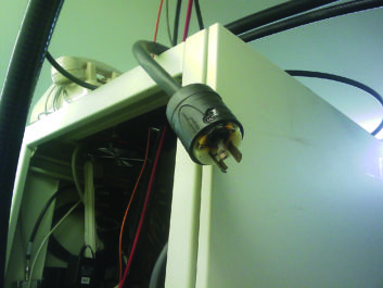
Once at the site, the engineer needed to do a little bit of sleuthing to find the problem. He began by tracing the AC power feed. The breaker was OK and measured voltage. It was not until he removed the power plug that he noticed the problem (Fig. 1).
Disassembling the junction box made it apparent that the screw terminal connections had been only marginally tightened. In the few years that the station had been on the air, the connection heated and oxidized until the resistance became high enough to finish it off.
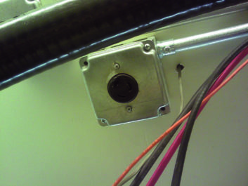
Once the junction box (seen in Fig. 2) was opened, it was apparent that the electrician who installed the outlet wasn’t accustomed to working with stranded wire. Fig. 3 shows how the connections heated and eventually failed.
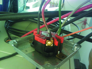
Another licensed electrician subsequently showed our engineer that when working with stranded wire, you should first tighten the connection, but then loosen it and re-tighten it. This process allows all the strands of the wire to deform and settle in a more compact manner.
Over the years, this tip has served him well.
***
The problem of overheating and the failures it can cause can be diagnosed using a relatively inexpensive infrared detector/camera. There are a number of expensive standalone IR models, but if you’re shopping in the $200-$300 price range, you may want to consider a smartphone solution.
Manufactured by FLIR or SEEK Thermal, these smartphone accessories are available from Amazon.
They display temperature on the smartphone screen using a color gradient. Blue images are cool; yellow, orange or red indicate increased heat.
Imagine being able not only to spot loose outlet wiring or circuit breakers about ready to fail, but also to identify loose coil clips or overheated capacitors in an AM array or loose elbow connections or junctions inside rigid transmission line.
Contract engineers may want to consider this addition to their arsenal of test equipment, offering analysis to clients for a fee. An annual thermal inspection would be good practice for all stations. And for liability protection, it would be prudent to use a licensed electrician to affect repairs uncovered by your inspection.
Spotting potential heat-related failures before they occur can save thousands of dollars — not only in repairs but in air time lost when a failure occurs in a critical equipment.
***
Every so often we get a neat tip from the folks at Platinum Tools. This company is well known for its Ethernet cabling and testing products. Their most recent release is a compact and handy RJ45 connector tester.
Ethernet cables, especially the eight-pin variety terminating in RJ45-style connectors, can come in enough varieties to make their termination particularly confusing. The VDV MapMaster 3.0 is ideal for anyone doing a lot of Ethernet cable work.
In reviewing their website, I discovered it is a wealth of cabling know-how. In addition to a blog and white papers, you’ll find how-to videos on cable prep and wiring subjects.
One of the neatest finds, however, was information on a free wiring tool. This tool comes with every piece of Cat5/6 cable and can be used to separate the individual wire pairs. What is it? It’s the piece of twisted pair cable jacket that you remove to expose the four pairs prior to terminating!
Using the “tool” is simple: Just slip it over each individual wire pair, one pair at a time; then as you slide the jacket over the pair, twist it in the opposite direction of the pair’s twist. Keep turning as you pass the sleeve over the pair, all the way down to the cable jacket.
To improve the performance, the folks at Platinum Tools suggest that you take your scissors and cut the end of the tool’s jacket at a 30-45 degree angle. The angled end makes inserting the wire pair easier.
***
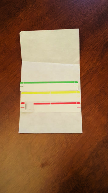
OK young’uns! Take a look at Fig. 4 and let me know if you can identify what these are. There was a time when they were commonplace at nearly all radio and TV stations. (It’s not fair asking anyone over 30!) My email address is below.
Contribute to Workbench. You’ll help fellow engineers and qualify for SBE recertification credit. Send Workbench tips and high-resolution photos to [email protected].
Author John Bisset has spent 50 years in the broadcasting industry and is still learning. He handles western U.S. radio sales for the Telos Alliance. He is SBE certified and is a past recipient of the SBE’s Educator of the Year Award.