In the Feb. 1 issue we began a discussion of the evolution of transmitter power supplies.
One of the more infamous radio transmitter motor-generator installations was in Las Cruces, N.M., at KOB, when it was part of New Mexico A&M College (now New Mexico State University).
(click thumbnail)
Kenotron diodes, originally designed by GE for powering X-ray tubes and electrostatic precipitators, were pressed into service to provide DC for some early transmitters. This 1920s photo shows the installation of multiple Kenotrons at Chicago’s WENR. Note the railing that separates operators and visitors from the high-voltage circuitry. The extended venetian blind cord provides evidence that this steel version of a ‘velvet rope’ didn’t provide that much of a barrier. Note also the water-cooling coils on the Kenotrons. As related by Ann M. Velia in the 1972 article “KOB: Goddard’s Magic Mast,” published by New Mexico State University, the station was founded in 1919 as 5XD by Dr. Ralph W. Goddard, who became the dean of the school’s engineering department and played a pivotal role in the station’s growth and development.
By 1929, KOB had developed into a 10 kW operation, and had FRC permission to jump to 20 kW.
Goddard was heavily involved in the design of the radio apparatus in use, and relied on motor generators for the transmitter’s DC voltages, using series-connected units (with frames elevated above ground) to achieve the necessary plate potential.
It’s reported that he watched over this early incantation of KOB like a mother hen, and kept a special wooden yardstick handy for whacking generator brushes to make sure that they were seated properly.
Ordinarily, southwestern New Mexico is quite arid, but on one particular day in late 1929, humidity levels were much higher than normal — so much so that the concrete floor of the outdoor generator room was damp, as were the soles of Goddard’s shoes and his favorite yardstick.
During a routine check of the generator room in the early afternoon of Dec. 30, Goddard tapped brushes of the 20,000 volt machine for the last time. The jolt he received was instantly fatal.
Without his nurturing presence, support for the station waned. It was moved and later sold off to commercial interests. (It has been in Albuquerque since 1932 and today operates as KKOB.)
In rotation
Rotating machinery and its upkeep requirements didn’t appeal to some transmitter designers.


Cooper-Hewitt mercury arc rectifiers were used to provide high-voltage DC power in some transmitters. In some cases, the operator had to manually rock the rectifier to start the arc. The tube shown is fairly small by mercury arc standards, being rated for 120 V service (at 30 amps); however it contains in excess of 15 pounds of mercury. General Electric engineers had their own ideas about developing high-voltage DC and borrowed technology developed by GE as an offshoot of William Coolidge’s research on hot cathode X-ray tubes, as reported in Dr. Saul Dushman’s article “A New Device for Rectifying High Tension Alternating Currents” in the General Electric Review of March 1915.
This was the Kenotron high-vacuum rectifier. (The word “Kenotron” was “Greco-Schenectady” nomenclature, borrowing from the Greek words for “empty space” and “appliance.”) The Kenotron initially was touted as a means for creating high-voltage DC for X-ray tubes and electrostatic precipitators, but found its way into several transmitter power supplies.
The Kenotron really wasn’t the perfect answer for broadcast transmitter applications, as it was intended for very high-voltage, fairly low-current situations and had a significant internal voltage drop. To provide the necessary plate current for even moderately sized transmitters, multiple Kenotrons had to be paralleled together. Evidence of this comes from the photograph of Chicago’s WENR early transmitter installation shown. A total of 18 type UV-214 Kenotrons can be counted in the “bay” between the clock and far wall. Existing documentation (I.J. Karr and C.J. Burnside’s article “Developments in Broadcast Transmitters,” distributed in the proceedings of an IRE convention in 1930) mentions that they were connected in a six-phase double “Y” configuration. Several other Kenotrons are visible in the photo.

Dr. Ralph W. Goddard, dean of the engineering school at New Mexico A&M in Las Cruces, founded radio station KOB. He initially ‘piggy-backed’ transmitter high-voltage DC from motor-generator sets in a college engineering lab before acquiring dedicated units for the station. Goddard became a martyr to early transmitter engineers when he was accidentally electrocuted by the station’s high-voltage motor-generator devices in late 1929. Photo courtesy New Mexico State University Library, Archives and Special Collections All of the tubes pictured are equipped with water-cooling coils. The internal voltage drop was so great as to require cooling for the Kenotrons, adding to the overall complexity of the transmitter.
Pounds of mercury
Another AC-to-DC device available to early broadcast transmitter designers was the Cooper-Hewitt rectifier (also known as the mercury arc rectifier).
While it depended upon ionization of mercury for its operation, any resemblance to more modern mercury vapor rectifying tubes stopped there. The Cooper-Hewitt device was based on the principle that when an arc was drawn between a conductor and a pool of mercury in a vacuum environment, current flowed in only one direction.
The “production model” Cooper-Hewitt rectifier came in several forms, but all were built around a reservoir containing several pounds of liquid mercury, and having at least two electrode-containing “sidearms” attached.
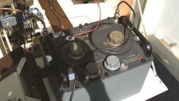
(click thumbnail)
These motor-generators supplied power for KOB. A station control room window provided a view of their operation. Photo courtesy New Mexico State University Library, Archives and Special Collections To start the rectification process, smaller models were energized and then rocked side-to-side until the sloshing mercury made contact with a separate “ignitor” electrode, thus initiating an arc. Physically larger units incorporated an ignitor electrode assembly that could be moved outside of the containment vessel by an electromagnet, thus allowing the initial arc to be drawn remotely. Once the mercury surface was “arced” and ionization began, the tube could be left alone, with the electrodes in the sidearms serving as rectifier tube plates and the mercury pool as the cathode, thus providing full-wave rectification. (Larger tubes with multiple sidearms were built for polyphase AC rectification applications.)
While the Cooper-Hewitt rectifier was a step forward in obtaining DC for transmitter plate supplies, it too was far from perfect, requiring frequent operator attention. (The writer once viewed an early broadcast transmitter with such a rectifier — a small “steering wheel” was provided for the technician to rock the glass vessel as part of the sign-on procedure.)
Another problem, though not considered that great 80 or so years ago, was the volume of mercury in the rectifier. The rectifier vessel was usually glass, and the sidearm electrodes were the weakest part. If mercury arc rectifiers were mishandled, it was easy to snap off a sidearm and release several pounds of mercury onto the building floor. The rectifiers could also explode on their own, creating an equally nasty problem.
The “sizzle” of the arc necessitated some careful design work in the power supply filter area.
Mercury vapor tubes
(click thumbnail)
Mercury vapor rectifiers replaced motor-generators in providing transmitter high-voltage DC. Shown here is part of a three-phase power supply used with a shortwave transmitter installed in 1938 near Munich, Germany. OSHA would probably not have approved. Photo courtesy James O’Neal collection The Cooper-Hewitt mercury arc rectifier eventually morphed into the hot cathode mercury vapor rectifier, which ultimately eliminated the high-voltage motor-generator sets needed for plate voltages.
However, these tubes still needed special handling and were not exactly foolproof either. More than one young radio engineer learned the hard way that they had to be “conditioned” before being placed into service.
This meant operating them for some time with only filament voltage applied. This heated up and vaporized any liquid mercury that might have lodged between internal tube supports or elements during shipping or storage. If “un-conditioned” tubes were hit with plate voltage, the accumulated mercury could cause a heavy short circuit with predictable results.
Even when well-treated, mercury vapor tubes could still misbehave. Occasionally, and for no apparent reason, they could “arc back” (short circuit) while in operation. The behemoth WLW transmitter used six giant mercury vapor bottles, and when one of them fired back, operators reported that the building shook. The utility company supplying 33 kV AC to the building was also immediately aware of the situation.
Solid-state, 80 years ago
Solid-state technology eventually put an end to rotating machinery and mercury-filled devices for providing transmitter DC voltages. This came about in the late 1950s and early 1960s, and was driven by the advent of the transistor.
(click thumbnail)
Silicon rectifier stacks such as these made by Wilkinson began to displace the beloved mercury vapor tube in the 1960s. They weren’t nearly as entertaining to watch. These two units replaced the 866 and 575 MV tubes used in many transmitters. Photo courtesy James O’Neal collection However, it’s not quite true to state that there were no solid-state rectifying devices used earlier. The copper oxide rectifier was one of these, having been invented in the late 1920s and commercialized by several companies. But as it was basically a low-voltage, high-current device, the majority of Cu2O rectifiers saw service in lead-acid battery chargers and meter rectifiers.
There was one documented use of this technology in transmitters for providing DC plate potentials in the 1940s. Westinghouse grafted RCA’s Rectox copper oxide rectifiers (more at home in other applications) into its 5, 10 and 50 kW models, but only for tubes requiring 3 kV or less. Main plate voltage sources were supplied by more conventional technologies. (See R.N. Harmon’s “Copper-Oxide Rectifiers in Standard Broadcast Transmitters” in the Proceedings of the IRE from December 1942.)
And according to most reports, even in these lower-voltage applications, the rectifiers weren’t that reliable. The author was unable to locate any record of selenium rectifiers being used in high-voltage radio transmitter applications.
Silicon stacks to the rescue
It wasn’t until the advent of reliable high-voltage high-current silicon rectifiers that mercury vapor tubes finally began to be phased out of broadcast transmitter designs. At least one company, Wilkinson, made high-voltage silicon stack devices to directly replace the mercury-bearing rectifiers.
Silicon rectifiers cut electric bills and transmitter room heat; and they made life simpler — indeed, in some cases, safer. But they also eliminated an unintended transmitter power supply feature, a modulation indicator of sorts. As one transmitter engineer reflected on that loss: “There was always something very comforting and reassuring about watching the brightness of the mercury vapor rectifier’s glow change in step with the modulation.”
James O’Neal is technology editor for TV Technology and a frequent Radio World contributor. Comment on this or any article below or write to [email protected].