Fig. 1: 1-5/8-inch rigid line in the control room.

Fig. 3: Support clamps secure the monitor brackets.Fig. 2: The rigid line actually supports the control room monitors.
Rigid line in a studio may be not unusual, as shown in Fig. 1, but you’ve probably never seen a monitor mount like the one in Fig. 2.
Dave West, general manager of Mountain Country in Colorado Springs, Colo., and engineer Bryan Waters needed to mount monitors in the station’s new control room. They also had some pieces of 1-5/8-inch rigid line left over from the transmitter installation.
Marry the two and you get a unique, solid support system for your monitors.
Support clamps (Fig. 3) anchor the monitors to the pipe. Typical end flanges, screwed into the console table top and wall, secure the pipe, creating an engineering work of art.
***
Randall Davidson is director of radio services with the University of Wisconsin and WRST(FM) in Oshkosh. He writes that the engineers at WRST have come up with an economical and elegant application to serve as a tower light outage alarm.
WRST is a “half-time” affiliate of Wisconsin Public Radio and provides local student-produced programming at other times. The station operates with a 1973-vintage Gates FM1H3 1 kW transmitter (see Reader’s Forum in our April 20, 2011, issue). It broadcasts from an 85-foot tower on the roof of a five-story building. Even though the station’s license doesn’t require it, the tower is equipped with two steady-state red beacons on top, activated by a photocell.
The station uses a Burk VRC 2500 unit to take transmitter/tower light readings automatically, and the student operators manually take readings when they’re on the air. The problem comes when the station is running unattended with network programming during overnight hours. Specifically, how could workers be alerted in the unlikely event that both tower light beacons fail?

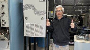
Fig. 4: A small solar panel is used to warn of tower light failure.
Chief Engineer Bill Kerkhof realized the infrastructure used for meter readings had unused inputs and thought perhaps one of these could be used to develop a tower light outage alarm. For less than $20, he purchased a small solar panel, shown in Fig. 4, typically used for charging wildlife cameras. This was installed in the station’s transmitter room and pointed out a west-facing window.
Testing indicated that it generated a positive voltage when the sun was up, but generated no voltage when it was dark enough to activate the tower light photocell. The solar panel voltage figure became another variable in the transmitter telemetry configuration.
Kerkhof wrote a short macro that would check both the tower light voltage and the solar panel voltage every 15 minutes. The possible outcomes are shown in the chart (below).

This final condition triggers an automatic phone call to the cellphone carried by the engineer on duty. By checking every 15 minutes, it gives engineers ample opportunity to contact the FAA should both tower light beacons fail.
The system is economical and reliable in that there are no batteries to renew and no moving parts. Should the solar panel itself fail during the day, the engineering cellphone would still be contacted, since both its voltage and that of the tower light photocell would be zero, a condition similar to the tower lights failing overnight.
***
Remember the “handle” we told you about, described by consulting firm Hatfield and Dawson? It permitted inverting an AM field intensity meter, so the antenna could be held close to the ground and used to “sense” AM ground radials.
Consultant Lewis Dye Collins writes that there is a finite probability that the bolt used to secure the meter in the Hatfield-Dawson grip could come loose, in which case the FIM could go crashing to the ground.
Some years ago, Lew had an FIM come loose from its “mooring,” so to speak, and the damage was not pretty.
A much safer approach is to make a small shielded loop antenna out of coax and affix the antenna to a broom handle or similar non-conductive rod. The loop is then connected to the auxiliary input jack on the FIM with a short length of coax cable.
This method permits you to carry the FIM right-side up, by its handle, and hold the test probe broomstick in the other hand.
Interested in this? Google “shielded loop antenna construction” for a variety of potential construction methods.
Contribute to Workbench. You’ll help your fellow engineers and qualify for SBE recertification credit. Send Workbench tips to [email protected]. Fax to (603) 472-4944.
Author John Bisset has spent 46 years in the broadcasting industry and is still learning. He handles West Coast sales for the Telos Alliance. He is SBE certified and is a past recipient of the SBE’s Educator of the Year Award.