You may have noticed neat antenna signs that we’ve featured in this column. They list the FCC Antenna Registration Number, warn of an RF Danger Zone (required by OSHA), or simply identify antenna coax cables with consecutive numbers.
The tags and signs are manufactured by Antenna ID Products in Glenmoore, Pa. Its Web site can be found at www.antennaID.com , or you can call (610) 458-8418 for a color brochure.
Typical antenna ID tag locations include the transmitter/radio, the entry port to the building, the coax halfway up and the antenna. These ID tags also serve as an inventory control system.
In addition to RFR signage, the company will prepare custom ID signs for fences, gate or tower road entrance signs, exposure guideline signs, as well as some unique license holders. The holders are either an 8.5-by-11 clear adhesive-backed plastic pouch – which permits affixing to the transmitter or equipment rack – or a high-quality clear plastic permits holder with bound and sewn edges and a hanging grommet for wall posting.
Antenna ID Products also sells guy-wire markers. You can alert snowmobilers, mowing operators or mud bikers of a low guy-wire hazard. The marker is composed of an eight-foot unbreakable plastic guard. It snaps over guy wires of up to 1 inch in diameter. Each marker includes three bands of night reflective marking.
Some towers may require a Guy Wire ID Ball. The ball is constructed of fiberglass with an orange coating. The halves bolt together, with supplied hardware, onto guy wires up to 3/4-inch diameter.
All of these products are great for marking your site, but my favorite is the Giant Coax ID Band. This identifier is a large yellow wire tie (1-1/2 by 13.5 inches) with up to seven letters or numbers imprinted on the band. Not only are these useful for identifying lines, but when labeled with your call letters, they could find uses in a remote kit.
(click thumbnail)Fig. 1: Make sure your tower is properly marked.
Fig. 1 displays some of the signs. Note that the FCC Tower Registration Sign is “FCC Approved.”

. . .
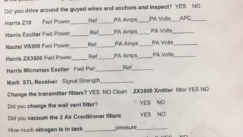
Here’s how to have a really big heart attack! Take length and width measurements of your transmitter building, in preparation for installing a new transmitter. It looks like everything will fit. Then delivery day comes, and the transmitter is shipped on a wooden pallet that won’t clear the entry door.
Once the transmitter is pulled off the pallet, you realize there are only a few inches from the top of the transmitter to the concrete ceiling.
(click thumbnail)Fig. 2: Check your measurements before the transmitter arrives.
Fig. 2 shows the heart attack material: only inches to spare. Fortunately, there was room for an elbow. Thank goodness that most harmonic filters are a part of the transmitter!
The close call brings up an important point. Transmitter manufacturers provide dimension drawings for a purpose. Use them to pre-install your transmitter on paper. Don’t forget about the height requirement.
You might also figure a 90-degree elbow, because there is a bending radius limit to all flexible coaxial cable.
If you don’t have a CAD program to lay out the room, cut out scale “paper dolls” of the transmitter, power supply and racks. Make sure you have adequate space to open doors, both front and back.
You might find that your calculations demonstrate you need a bigger building. Planning is the key. Take the time to analyze everything, so there will be no “heart stopping” surprises.

. . .
As most of us endure frigid temperatures, some lucky engineers are still enduring thunderstorms!
John Stortz from the Moody group in Sarasota, Fla., sent an e-mail recently, after recovering from yet another storm. Thunderstorms mean electrical surges, so even in the middle of winter, some engineers are dealing with surge suppressors and UPS systems.
John mentioned a good tip for us all to keep in mind. When installing surge protectors in line with a UPS, make sure the suppressor is inserted ahead of the UPS.
Most UPS systems do not have pure sine-wave outputs, and the harmonic-rich waveshape is likely to overtax or even destroy the surge suppressor over time. Size the suppressor to the load. At least one manufacturer, LEA, provides guidelines when specifying their suppressors for studio or transmitter use.
Finally, ensure that the suppressor has a good ground. Poor grounding prevents the suppressor from doing its job.
I’d like to add a tip of my own, for anyone contemplating the purchase of a surge suppressor. I tell my transmitter customers to contact their insurance company when considering the purchase of a suppressor.
Many insurance companies will lower premiums when a suppressor is installed. In my contracting days, I had some insurance companies actually pay for all or a part of a suppressor, due to the claims savings it would provide the insurance company.
Get the name of your station’s agent, and have a talk. Even a premium adjustment will make you look great in the eyes of your station management.
Submissions for this column are encouraged, and qualify for SBE recertification credit. Fax your submission to (703) 323-8044, or send e-mail to [email protected].