Two-thirds of the way into spring, it’s time – past time – to take a close look at what winter did to your outside cabling.
This includes inspecting the cables on the studio roof feeding EAS and off-air monitor antennas. Cables that rip loose from their supports can cause damage to themselves and adjacent antennas or structures. (No doubt this will happen in the middle of morning drive.)
We’ve driven home the point of not using white nylon cable ties because the ultraviolet light will cause them to fail. Black has a better track record; but even the black ties, in practice, aren’t much better than the white. After a couple years of wind, weather and sunlight they get brittle, break and let you down.
Jim Alexander is a contract engineer in Arkansas. He writes that his favorite technique for securing smaller lines is to use lengths of #10 or #12 solid-conductor copper wire with black insulation. Jim says any color will do; you could color-code feedlines with various colors of wire if you like. Wrap the wire around the tower leg and feedline a couple of times and twist with pliers. As an added benefit, you can re-use them several times if line feeds change.
Jim also wanted to comment on the nicked Heliax jacket mentioned in a previous column. Years ago, the crew at ERI was working on a tower and showed Jim the best way to repair a small hole in the jacket. They used a small piece of rolled roofing material, and some roofing repair compound, either tar, or plastic.
Cover the hole with the tar or plastic compound, then use hose clamp(s) as necessary to clamp the small piece of rolled roofing material over the small break or hole.
Jim can be reached at [email protected].
. . .
Fred Shetler, a ham and engineer in Port Royal, Pa., writes about the picture of the “log rest” in our column of April 7. Although it’s a good idea to help organize jocks’ logs, Fred identified a potential problem: the two sharp corners. They need a good radius on them.
Fred says he can envision a jock wounding the back of his or her hand in a rush.
No wounding has been reported, probably because the log rest is located at the far right of the console, away from most hand motion.
Reach Fred at [email protected].
Fred also asks for comment on the use of transmitter tubes in cold climates, essentially operating in an unheated plant. We’d like to get your tips and experiences. Send them via e-mail to [email protected].
. . .
Matt Krick is an engineer for KGMN(FM), KZKE(FM), KYET(AM) and low-power KKAX(TV), all located in Northwest Arizona.
He writes to tell Workbench readers about a shocking experience he experienced a couple of weeks ago.
When doing post winter maintenance on his stations, he was at KGMN, which uses a Harris FM-1K transmitter. Matt noticed that the plastic cover on the Plate Current meter had fallen off and was lodged between the area where the meter sits and the front chassis.
Thinking nothing of it, he picked up the plastic cover and tried to place it back on the meter, while the transmitter was still on.
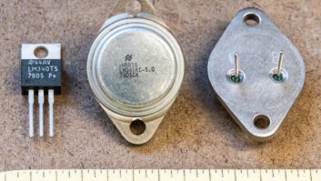
(click thumbnail)Fig. 1: Check the location of meters in the circuit before touching them.
It was only after that Matt realized why the cover was off in the first place. One of the terminals was conducting to the meter’s faceplate and just waiting for someone or something to come into contact with it.
Matt’s hand came in contact with the meter and took the full force of the 3 V plate power supply into his left index finger.
“It was like having a camera flash go off in your face, followed by severe pain about five seconds later,” he told us. There is a crater on the faceplate where the arc occurred, just below the 0.1 amp position.
The experience left a pretty good electrical burn on his finger where the contact was made to chassis ground. Thinking fast, Matt threw his hand into some snow that hadn’t finished melting. He waited 30 minutes for enough feeling to return to his hand so he could make the drive down the mountain. Slowly the feeling to his fingertip returned.
When he replaced the meter on the day after the incident, it appeared that a small fire had occurred in the original meter. There were char marks all over the place.
(click thumbnail)Fig. 2: A dusty ‘haze’ is a tip that the meter is at a high voltage potential.
The experience taught Matt a number of good lessons: First, check schematics to see where meters are in circuits; assume nothing. After the incident, Matt checked the schematic and saw the ammeter was in series with the high side of the plate circuit. The dusty “haze” seen in Fig. 2 is another tip that the meter is at a high voltage potential. The high voltage attracts the dust that clouds the meter face.
When cleaning these meters, make sure the transmitter is off, and all high-voltage points properly discharged.
Matt also cautions readers to have a buddy present when working on transmitters. We’ve all “done it alone,” especially in an emergency; that doesn’t mean it’s right. Last, the experience has taught Matt – and should teach us – to think twice before “thunking” a meter with a thumb.


. . .
Ihor Slabicky works for Raytheon and saw our April 23 mention of the woes of soldering RCA plugs. Ihor offers some tips for soldering these connectors.
First, fold the tip (center, hot, +) wire over on itself before inserting it into the center tip. The fold should form a sort of “spring” effect, so that when you stick the wire in the center, there is enough pressure and friction to hold the wire in place. If the wire is thick, you can put a wiggle bend in it, so it still gives a friction fit.
Stick the wire in all the way, so it is flush with the opening, or even sticking out about 0.5 mm.
It helps to have the shell of the connector wrapped in some kind of heat sink. Ihor uses a piece of damp paper towel, wrapped around the shell and the insulated part of the wire going into the center. The damp towel guards against melting the insulation.
Once the wire is firmly in place in the center pin, heat the open tip of the connector and the 0.5mm piece of wire sticking out of the end. Have your solder ready. Use a very thin solder, so it melts quickly. As you heat the tip and the wire, lightly tap them with the solder, to see if the temperature is high enough to melt the solder.
As soon as you see that the solder is melting, push it into the center hole. Heat a little more, let the solder melt nicely then let it cool. You should end up with a nice round shiny blob of solder, the same diameter as the center tip.
The process takes practice, but is worth learning and doing well. Use less heat and more patience. You’ll get good connections and won’t melt the insulation of the center wire.
I’ve also found that tinning the center wire before starting the procedure helps in securing the wire to the inside pin of the RCA plug.
Thanks, Ihor, for sharing these tips.
Submissions for this column are encouraged, and qualify for SBE recertification credit.