AM Radial Sniffer
May 11, 2005 12:00 PM
When the performance of an AM antenna diminishes and the ground system is suspected as being the problem, it is common to ensure that the copper radials are intact for the entire ground system. A common way to find the radial is to use a field-intensity meter, such as the Potomac FIM-41, to sense the RF signal. By holding the unit close to the ground and sweeping it from side to side, a bump in the RF signal can be observed.
The FIM acts like a stud finder. The peak of the signal indicated the location of the radial. If the signal from the radio stops short of the expected distance, there is a likely a break in the copper wire.
Stephen Rutherford, chief engineer at Archway Broadcasting in Columbus, GA, suggests some simple modifications to enhance the performance of a FIM-41. He suggests inserting a small sheet metal screw into the gap of the lid to short the Faraday shield and desensitize the unit’s antenna. Then, he recommends using a piece of 1/4″ x 20 all-thread, some nuts, washers and a piece of wood, make a tee handle for the meter.
The bottom of the FIM-41 has a threaded hole to mount it on a tripod. By inserting the tee handle, the meter can be held upside down. Cut the all-thread to the proper length for your height so the meter is about 3″ or 4″ above the ground when held by the handle.

Rutherford says to plug headphones into the FIM and listen for the peak in the audio as the meter is swept from side to side. The peak indicates to location of the radial.
Rutherford also suggests using the wire marking flags like those used by utility companies to mark the location of the radials. You can also use the marking paint, which can also be used to further indicate trouble spots.
After the radials have been marked, remove the handle and the sheet metal screw from the FIM to return it to normal operation.
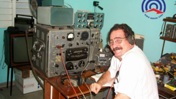
Scott Todd at KKMS has a different method. He uses a tuned-loop antenna, a diode, a capacitor and a sensitive meter.
He uses a quilting loop from a craft store. He winds several turns of #24 wire around it. Using a salvaged tuning capacitor, he varies the wire turns and cap tuning to find the point of resonance. He insert the diode in series with the loop to feed the meter. He also places a 0.001 to 0.01 �F capacitor across the meter connections.
If the meter is too sensitive, add some series resistance to the antenna.

Scott Todd’s tuned loop apparatus

The switch adds a resistance to the circuit to change the sensitivity.

The tuning adjustment sets the resonant frequency of the system.