Kintronic Labs Kinstar
Apr 1, 2009 12:00 PM, By Tom F. King
More and more communities and neighborhoods across America are growing tired of the proliferation of cellular telephone towers, resulting in the establishment of revised local zoning laws for new structures that reflect a lowering of the maximum allowable height. Star-H Corporation and Kintronic Labs are now able to offer a solution for AM non-directional station operators. The Kinstar antenna conceived by Star-H Corporation, particularly Dr. James Breakall, professor of electrical engineering at Penn State University, was developed into a marketable broadcast product by Kintronic Labs. The Kinstar was officially type-accepted by the FCC on October 25, 2005, for full-time omnidirectional operation in the AM band in the U.S. market in accordance with Public Notice DA 05-2741 entitled Media Bureau Adopts Simplified Application Procedures for AM Nondirectional Kinstar Antennas.

Figure 1. Kinstar antenna final design configuration using lumped element matching and with top and bottom of vertical radiating wires connected together. All antenna wires are insulated from ground and supports.
Click to enlarge
On Jan. 11, 2009, the first Kinstar antenna was placed on the air by KCST-AM in Florence, OR, operating on 1250kHz with 900W daytime power and 37W nighttime power. KCST owner, Jon Thompson, needed to replace his 57.89 meter tower. His contract engineer, R. Sparks Scott, recommended he consider the Kinstar antenna, which, following further investigation with his consulting engineer, Bob McClanathan, P.E., he decided to install at a location 1.3 miles northeast of his old tower site. As his frequency of 1250kHz, he has a maximum height above the ground of 70′ with the Kinstar, which fit well with the local zoning height restriction of 72′. Also realizing he would have no tower painting required with the Kinstar, Thompson saw the decision to go with the Kinstar as a logical move that would save substantially on long term maintenance costs.
The Kinstar antenna design licensed by the FCC as a top-loaded antenna is shown in Figure 1.

Figure 2. The feedpoint of the KCST Kinstar antenna showing three of the four insulated vertical elements with the associated communing ring and the Kintronic Labs Model LTU-1B-1600 antenna matching unit.
The KCST Kinstar was designed in accordance with the scaled electrical dimensions defined by the experimental antenna operated under FCC experimental license WS2XTR for operation on 1680kHz. With an electrical height of 63′ and top loading of 134 feet the KCST Kinstar operating on 1250kHz was installed with five 85′ wooden utility poles, and standard pole line hardware and cable in one and a half days by a utility company out of Portland. All of the anchors were screw anchors buried in the soil using a hydraulically-driven auger; therefore, no concrete was required in the installation. A 120-radial quarter wave ground system was installed following the antenna installation.

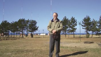
Figure 3. View of the KCST Kinstar antenna with the center feed at the left, three of the five total support poles shown and the transmitter building on the right with the STL dish installed on the pole closest to the transmitter building.
A photo of the feed point at the base of the center pole of the Kinstar antenna is shown in Figure 2. An overall view of the KCST Kinstar antenna is shown in Figure 3.
With the height of the Kinstar pole supports falling below the average height of trees in the nearby forest, the antenna blends into the background rendering it invisible to the passers by on the coastal highway. As a result, the Kinstar is clearly an environmentally friendly antenna technology.
Kintronic Labs Kinstar
Apr 1, 2009 12:00 PM, By Tom F. King

Figure 4. KCST-AM Kinstar antenna drive impedance measured at the output J-plug of the antenna matching network by Bob McClanathan, PE.
Click to enlarge
Another advantage of the antenna is the wide audio bandwidth it offers in comparison to the typically narrow band characteristics of electrically short AM antennas. Figure 4 illustrates the small change in resistance and reactance of the KCST Kinstar measured over the 1250 �15kHz band.
The inherent audio bandwidth performance of the Kinstar is evidenced by the less than 2 ohm variation in R and the less than 10 ohm variation in X over the 30kHz bandwidth of a typical HD Radio channel. Following the initial antenna tune-up and commissioning of the transmitter operation into the antenna Bob McClanathan responded, “This past Sunday, Jan. 11, I worked with Jon Thompson and Sparks Scott at KCST in Florence, OR, to complete the ATU adjustments and measurements for their new Kinstar AM antenna. I am very impressed with the quality of the antenna construction, and the operation is much better than what I expected. The impedance at 1250kHz is Z=15.1 + j80.0 ohms and is flatter than a pancake �20kHz. Would be excellent for IBOC but fortunately KCST is not going there.
“The Kintronic ATU is of excellent quality as usual and built for easy impedance measurements. Very little adjustment was necessary to set the T for Z=50 � j0 at the transmission line input. The KCST Kinstar is excellent in performance. I met a neighbor near the antenna site who is very pleased with the unobtrusive and nearly invisible appearance of this antenna. When considering the FAA restrictions, local zoning and neighborhood objections, this Kinstar will certainly prove valuable and popular for non-directional AM antenna sites.”
King is president of Kintronic Labs.