Maintaining directional antennas
Jan 1, 2005 12:00 PM, By John Battison, P.E., technical editor, RF
It is unfortunate that the most important link in any AM radio station’s system is frequently ignored for years at a time. The directional antenna is the last link in the chain between the studio and the listener. If the DA system is not properly maintained and its operating parameters fail to comply with the terms of the license, the losses can include lost income and FCC fines for failure to comply with the rules. The most important thing is to be systematic in one’s maintenance plans. On joining a new station, the latest proof of performance of the antenna system should be examined. This is what the FCC will demand to see during an inspection. The operating parameters and this document must agree with the license on display. If there is no license on display, get one immediately. If the latest proof of performance is not available, get one from the consulting engineer who tuned the antenna system.
Basic operation
The common point is the input to the phasor, which is the heart of the DA system. The current and input resistance through the system measured at this point determines the power of the station, and their product must agree with the license.

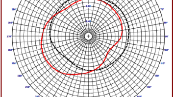
Physical changes in the antenna system can affect a directional array, but it is equally important to inspect tower fences and clear ground vegetation.
As time passes, components age, connections loosen and corrode, coil taps tend to fail, gas and vacuum capacitors leak and transmission lines leak and sustain damage, or may have their lengths changed. Sampling lines suffer similar problems. In addition, ground systems deteriorate and are lost through chemical action, vandalism or theft of the copper wire and insulators crack. A common problem is caused by improper guy wire maintenance so that the wire becomes part of the radiator and changes its electrical length. Outside the electronic system, vegetation can grow around the base of the tower and change the base operating impedance. This is just a small list of the items that can, do and will change in the average DA system.
Before the days of 24-hour operation, it was possible to perform a daily heat check. Now that most station transmitter sites are not inspected daily, this is not possible, however, the heat check is a great way to find potential problems before they becomes significant failures. Whenever visiting the station, feel the transmission lines, capacitors cabinets and anything else that should not get hot. Keep in mind that this quick check should not replace a regular maintenance schedule.
Every station has different requirements, but if the following list is checked monthly you should be able to catch any major catastrophes before they occur.
- Confirm that all meter readings agree with licensed values
- Confirm that the antenna monitor readings are correct
- Examine the base insulator for cracks, lightning carbon tracks; check ball gap
- Check the transmitter operating log
- Check dog houses for rodents, insects, dirt, hot components and signs of heating.
- Examine the switch contacts, RF line and connection to tower. Be sure there is at least one turn 18″ to 24″ in diameter between the tower and the doghouse
- Inspect lighting chokes and static drains
- Check the tower lights and photocell operation
- Check all monitor points if required; look for trends, take any required action
- Check the guy anchors and turnbuckles to ensure that lock wires are in place, the turnbuckle is secure and the anchors are sound.
The common point current should be checked and the calculated RF power should be compared to the calculated efficiency of the final stage to confirm that it is reasonably correct. In the event of doubt, the common point impedance must be checked with an operating bridge with power adjusted for the power capacity of the bridge. If the array operating parameters are correct but the common point power (the product of the impedance of the common point multiplied by the square of the common point) is incorrect necessary adjustments must be made. The common point impedance is controlled by the shunt arm of the common point tee network. The common point impedance should be set to the licensed value and transmitter power adjusted accordingly.
The tower environment

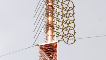
It is important to check the tower base insulator, spark gaps and tower feedline regularly.
Don’t neglect the tower environment, that is the area around the transmitter site. If your DA sites are visited only rarely, check for new tower construction on each visit. If any is found, locate the licensee and check records to see if the FCC required a pre-construction pattern interference check. Then follow through to ensure that your pattern is protected. Once these towers are up and running, it is often much harder to get compensation and correction.
When checking monitor points, look for new towers or construction in the vicinity of points that are out of limits. If there is nothing in the area to account for the monitor point change, don’t touch the phasor controls. Look at the adjacent points in the proof. If the entire radial is up (it’s not usual for them to be down) recheck the transmitter power output. Check the points on each side of the monitor points in question and compare the power and other monitor points on other radials. If only one radial is high, check the operating parameters carefully � especially base operating currents. Look for potential reradiators in the vicinity of the DA, such as a small towers and metal buildings. Use a field intensity meter to determine the azimuth of the maximum signal to see if it is coming directly from the transmitter.
Resist the temptation to adjust the phasor. If you feel you absolutely must twiddle a knob be completely sure that you have written down every phasor dial setting in several places before turning any knob. Never move more than one at a time or you won’t know what caused the change. Sometimes a combination of several parameters at maximum limits in the same direction can raise a radial by shifting a null slightly.
E-mail Battison at[email protected].