In the precious little spare time available to me, I sometimes find myself being drawn to science fiction and fantasy literature. I know I know it offends the sensibilities that a geeky engineer would, on occasion, delve into such recreation, but tales of valiant heroes, fair maidens and magic provide an escape from the sometimes harsh reality that is broadcast engineering.
One of the most enduring legends is that of the mythical unicorn drinking at the waterfall surrounded by rainbows. The modern-day broadcasting analog to the unicorn is the non-directional antenna, and like that noble creature of lore, it does not exist.
An example of a two-bay nominally non-directional antenna in radomes. To be sure, we all give Non-D radiators lip service, but none of us can actually construct one in reality. This is true whether we are talking about AM or FM antennas. Indeed, should any of us be able to actually fabricate such a construct, I submit that the concerns of the day would become sand and sun on some tropical island rather than the practice of our current art.


Recently the question of directional versus non-directional has reared its ugly head once more.
The issue at hand is a station in Texas where techniques and apparatus were utilized to ostensibly create a pattern that is more omni-directional than would typically result due to tower interaction. The perceived result is that one station wound up with better rim-shot coverage into a heavily populated region, while a co-channel facility on the opposite site of the metro is being pounded by interference. The complaint, of course, is that the non-directional antenna utilized is not really non-directional and was heavily engineered to distort the pattern.
It should be axiomatic that mounting an antenna to a large metallic mass, i.e. a tower, is going to cause distortion in the radiated pattern. You know this, I know this, the antenna manufacturers certainly know this, and whether they want to admit it or not, the commission knows this. The reality is even the naked antenna in free space is going to have some directional characteristics to it. The tower exacerbates this situation.
BACKSTORY
In 1984, the Federal Communications Commission issued a Public Notice discussing the criteria for licensing of FM Broadcast Antenna Systems. In that notice, the commission stated it ��assumes that FM non-directional broadcast antennas have perfectly circular horizontal radiation patterns.� The knee jerk response to this statement would be to ask the commission what color the sky is in their world. However, if we take a more circumspective approach, we can actually see the wisdom behind that statement.
How much computing power did you have in 1984? If you were like me, you may have had an Apple II+ with 48K of RAM, or maybe a PC. The point being, computing resources were not as pervasive then as they are now, and having to consider each and every pattern as it truly is would have taxed stations and the commission unduly. Furthermore, there would have been significant amounts of squabbles over the veracity of submitted data. By making the pure non-directional assumption, the commission quelled those arguments, and more or less leveled the playing field.
A four-bay directional antenna with parasitic elements in Bloomington, Ill. Of course, in the end, the commission did leave itself an out, even from the occasional malcontent. Section 73.209 specifically points out that permittees and licensees are not protected from interference, except from Class D stations, that may result from the grant of new stations or modifications made in accordance with Section 73. This section is a recognition that station coverage does not end at the protected contour, that terrain is irregular, the geographic spacings method is imperfect, and implicitly, that there ain�t no such thing as a truly omni-directional antenna.

So the question of the day is when does a �non-directional� antenna become directional?
The 1984 Public Notice states ��any technique or means (including side mounting) which intentionally distorts the radiation pattern of what is nominally a non-directional antenna makes that antenna directional and it must be licensed as such.�
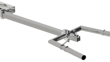
Adding parasitic elements and utilizing non-standard mounting brackets would seem to definitely fall under attempts to distort the pattern. But what about side mounting? Ideally, every FM antenna would be mounted to a pole on the top of a tower. Such a scheme would ensure the greatest circularity of a given pattern. That is, of course, unrealistic. Not only would this pose certain structural concerns, but it could easily substantially increase the required number of sticks to accommodate all stations. This would most certainly give heartburn to the trifecta of local zoning officials, concerned residents and environmentalists, not to mention the concerns of the FAA.
The reality is that there are necessarily going to be antennas mounted to the side of a tower. This includes leg and face mount configurations. Each will affect the pattern to a different degree, and tower face size plays a large role in that.
A number of years ago one of the major antenna manufacturers released a software package that allowed you to estimate the impact of the structure on an FM antenna. Their package allowed for consideration of pole-, leg- and face-mount configurations. The program also considered frequency of operation and face size, if applicable. In perusing their pattern library, I noted that the maximum estimated relative field values tended to be at 1.6 or less. This means that they are estimating the pattern maxima to be within approximately 4 dB of circular. That is a pretty huge difference, but honestly is not that far off of the values in the current Texas case.
Historically, it seems that somewhere between zero and three dB off of circular is where the commission tends to draw the line. In 1983, the commission in a Memorandum Opinion and Order, colloquially referred to as �Ettlinger,� refused to grant a proposal where the peak gain was 3 dB above circular. In this particular case, the applicant used a nominally non-directional, but optimized, antenna to meet the community of license coverage requirement while simultaneously serving a heavily populated area. In this case, although the applicant specified the antenna as non-directional, it instructed the manufacturer, in essence, to distort the pattern to achieve the desired 3 dB gain. That seems to be a pretty clear-cut case of overt attempts at distortion even if the values are less than those being bantered around in the current complaint.

The more problematic situation that could arise out of this whole proceeding is active enforcement of a somewhat arcane portion of Section 73.211(b)(1). That section states that unless your station is in Puerto Rico or the Virgin Islands, the maximum ERP in any direction is listed in the related table. This has the potential of being a huge game changer for nearly all stations licensed as non-directional. Instead of relying on the RMS gain of the antenna to determine the effective radiated power, licensees would have to consider the peak gain of an antenna. This would require each and every antenna to be range tested or scale modeled to determine the actual gain so as not to run afoul of the rules. The result is that new TPO values could be half of what would be expected normally.
As of writing, the Texas case is still pending, with the response to the show cause order due about press time. Some of the pleadings in the case indicate that the complainant may have also engaged in similar tactics of pattern distortion. Quite honestly that would not be earth shattering, as I would wager the trajectory of a rotating deceased feline on the floor at the recently completed NAB Show would intersect no less than a half-a-dozen similar dudes. That being said, I am anxiously awaiting to find out if this current case throws open Pandora�s Jar (Yes � it actually was a jar), or whether the dogs roll over and go back to sleep.


