In part one of the series, I discussed the essentials of PLCs, took a brief look at the internal structure of the PLC, considered programming methods — the most common of which is “Ladder Logic,” and hinted at the software to program the PLC. In this part, we’ll set out to get an inexpensive PLC up and running.
Click PLC programming cableAUTOMATION DIRECT

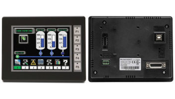
There are many vendors and sources of PLCs: Automation Direct, FactoryMation, B&B Electronics, and yes, even eBay, among others. I will use the Click PLC available from Automation Direct as an example in this article.
The specific CPU I’ll discuss here is their model C0-00DR-D, which features eight digital inputs and six relay outputs with 1-amp rated contacts. Also featured in this PLC are two RS232 Serial ports.
There are other versions, which are slightly more expensive and include RS-485 and/or an Ethernet port. This DIN-Rail mounted CPU is powered by a 24 VDC power supply. You can use either their matching DIN-rail mounted C0-00AC 24V/0.5A unit or your own favorite regulated supply. The CPU sells for $69, while the power supply sells for $29.
One note about PLCs: The total of the inputs and outputs of the PLC is referred to as “points.” For the Click PLC mentioned here, the combination of eight inputs and six outputs makes this a 14-point PLC.
PROGRAMMING SOFTWARE AND GETTING CONNECTED
The free software can be downloaded here.
There is also a collection of Click startup videos, which can be found here.
I suggest you download the free software, install it and explore its features a bit. Much as with any programming software, PLC software takes a bit of practice in order for users to truly become proficient.
This particular PLC has 2 RS-232 ports. Port 1 is used to interface to the PC running the programming software while Port 2 may be used to communicate with other PLCs (via ModBus commands) or to communicate with an HMI display or a PC running SCADA (Supervisory Control and Data Acquisition) software. I suggest you purchase the $14 factory-made data cable which uses an RJ-11 connector on one end for the Click serial connection and the familiar DB-25F connector for the PC. As serial ports on PCs have become less common, you may also need an inexpensive USB-Serial adapter (it’s always good for a broadcast engineer to have USB-Serial cable on-hand in any case).

“The documentation which is available in PDF form as well as the instructional videos I mentioned earlier will guide you through the initial connection process. The PC should negotiate the serial parameters as defined in the Click.” I’ve thus far have not needed to go into the hardware settings in Windows to make any changes.
INITIAL PROGRAM WITH THE PLC
We’ll start with a simple test program which will use the PLC as a latching relay and add more features as we go. Let’s examine the code in the screenshot.
The Click PLC identifies physical inputs (that is, the actual electrical inputs on the terminals of the PLC) with “X” and physical outputs as “Y.”
The model PLC we’re evaluating here has eight inputs designated as X001 through X008 and the outputs numbered Y001 through Y006. I need to point out that, in order to make the ladder program more readable and easier for you to understand, these “X” and “Y” I/O points can be given nicknames such as: “Transmitter 1 On” and “Blower Motor Control.”
In addition to these physical I/O points, there are (get ready to be amazed): 2,000 control relays; 1,000 system control relays; 500 timers; and 250 counters — all of which are in fact, simply bits in memory addresses (a fact I mentioned in earlier articles and which is a key point to remember in order to avoid confusion). In addition, common programming constructs such as subroutines, for-next loops, interrupt handling, math operations and sequencers* are available.
SAMPLE PROGRAM DISCUSSION
OK, let’s see what we made here.
Starting with ladder line one, and going from left to right, we have external digital input X001 connected to C1. When input X001 is asserted, C1, which is used here as a set coil, turns on. On line three of the ladder diagram, C1 is instantiated as a normally-open contact and when closed, turns on output coil Y001. This output coil can conduct up to 1-amp and can be used to turn an external device on. When input X002 is asserted, we reset C1, the contact opens and Y001 switches to off.

In an earlier paragraph, I mentioned there are 2,000 control relays, all of which are just bits in the PLC memory. C1 is one of these. Control relays can be configured with many different attributes. For example, they can be set to be retentive, which maintain their state even during a power loss to the PLC; or they can be used as “edge contacts,” which will react to either a rising-edge pulse or a falling-edge pulse when instantiated as a contact.
One word I will use throughout this series is “instantiate.” This is a verb that means to turn something abstract into something real. When I instantiate C1 as a coil, it means that I’m taking a memory location and assigning it to an object that will be placed on the ladder.
When instantiated as a “coil,” C1 can be used as an on/off device, or, as used in the sample program, a set/reset latching device. (That’s just one more attribute that can be assigned to that control relay C1.)
It may help to think of this control relay C1 as the coil of the relay when used as an output on the right-side of the ladder diagram, and as one of the associated contacts of that coil when used on the input, or left-side of the ladder diagram. And here’s a vital point about the power of this program: C1 can be used a coil with hundreds of normally-closed or normally-open contacts when instantiated anywhere on the left-side of the ladder diagram.
What this also means is that you can “rewire” your system with mouse clicks — rather than with a soldering iron and wire cutters.
With a couple of clicks I can change C1 from having two output contacts (for example) to one having say, five output contacts. I can make them all normally open, or all normally closed, or I can mix them anyway I want. You could also think of this as a logic device (an AND gate) which has multiple inputs, and also, if I want, multiple outputs.
FURTHER DISCUSSION
To be sure, the sample program is trivial and meant solely as quick demo of the PLC. If you examine the brief overview of the click specifications I outlined above, it is clear there is a great-deal of capability available. You can declare the inputs to the PLC to be standard on/off inputs, or “pulse-catch,” which allows the designer to actuate a de-bounce filter or to declare the input to be an interrupt initiator. (Interrupts are useful if you need a priority handling routine in your program to immediately divert the PLCs attention to a critical process — think of a big red Emergency Stop button). Should you need to add inhibit action in a line of ladder code, you can add a normally-closed contact from one of the inputs in series with the X001 contact which, if actuated, will prevent the external device from being turned on (think of an interlock or a limit switch).
INTERNAL AND SYSTEM CONTROL RELAYS

A very useful set of built-in control relays (again, not physical relays — memory registers) are available for you to use with the Click (and most other PLCs). These save you lot of time and thought by not attempting to create your own.
Some examples are: Real-Time Clock, 10ms, 100ms, 500ms, 1-sec, 1-min, 1-hour pulses, watchdog timer, battery status, various PLC error flags, data port status flags and PLC status flags.
One of my projects was a directional antenna controller with an automatic pattern change feature which made use of the PLC’s RTC and its internal comparators to match real time with entries in an internal data array table in order to perform the automatic day/night pattern change.
So far, we have covered some internal architecture and operating system of the PLC; we’ve suggested where to purchase your first PLC, discussed where to get the software, and finally how to get connected to the PLC. In this article (second in the series), we’ve designed a simple program to test the PLC and discussed the powerful instruction set which you have available to you.
Next month, we’ll go into more depth discussing various programming methods, some tips for a more stable running program and something called “tags.” As the programs become more complex with hundreds of lines of code, some good practices should be followed in order to avoid unexpected results and I’ll discuss them.
FOOTNOTE:
*Sequencers are also known as “Drum Sequencers.” Think of the timer in your laundry washing machine as it sequences through the various cycles based upon time and/or external input. The PLC Sequencer is a function block which emulates this action digitally with precise control which may be event-driven or time-driven (or a combination thereof!).