The author is with Radio Engineering Services.
Just off Long Island Sound lies Bridgeport, the largest city in Connecticut. With more than 145,000 residents, the gritty industrial feel of Bridgeport is surrounded by picturesque suburbs. It is also close to the nation�s busiest city and lies near several smaller metropolitan areas.
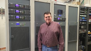
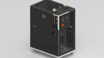
Dave Supplee of Cumulus and Peter Partineo of RES stand in front of WEBE�s new FLX-40.
Photo Credit: Brian Galante, President, Dimension PR

These are attractive attributes for a radio station like WEBE(FM), the 50,000 Watt Class B station broadcasting to southern Connecticut on 107.9. With a pool of ad support around five metropolitan areas, WEBE remains dedicated to serving and growing its listener base.
Technical infrastructure is naturally an important part of that strategy, and WEBE is one of nearly 70 Cumulus radio stations earmarked for an RF investment. At most of these sites, the main initiative was to reduce operational expense and energy use, with an emphasis on long-term sustainability.
Nowhere was this more critical than the WEBE plant. Co-located with the Bridgeport Energy power plant � a six-bay, half-wave-spaced Shively antenna rests near the zenith of a 500-foot-high, coal-fired smokestack � the transmission infrastructure recently showed signs of age. The station�s two Broadcast Electronics FM35A tube transmitters, which long served the station, required an increasing amount of care associated with tuning and overall maintenance, and cooling requirements and power bills continued to escalate as the transmitters chugged along.
Efficiency matters, and there comes a time when an overhaul is needed. Given the unusual traits of the facility (location, TPO and cooling needs), WEBE needed to make big changes to its RF infrastructure to meet efficiency goals. A transition from an air-cooled to a liquid-cooled system quickly rose to the top of the list.
A REIMAGINED FLOOR PLAN
Radio Engineering Services was hired for all turnkey services related to the new transmitter project, including commissioning and installation phases. The first order of business was to evaluate the existing transmitters, which we did in tandem with the Cumulus team led by Dave Supplee, senior regional director of engineering. The RES team included myself, owner Dave Growth and engineers Peter Partineo and Tom Morgan.
Though operational, the main FM35A was in steady decline. We stripped the transmitter of its parts and retained them for the backup FM35A. As an older tube transmitter, the FM35A�s sizeable footprint is accompanied with a large 500-pound plate transformer. Removing these racks and cabinets returned a generous amount of real estate to the plant. The removal of these units also allowed us to eliminate older wiring and RF filtering not required for the new system.
Following evaluations of high-efficiency, solid-state transmitters on the market, the Cumulus team zeroed in on GatesAir�s Flexiva FLX-40 liquid-cooled transmitter. The FLX-40 is part of a larger purchase from GatesAir that included FAX air-cooled transmitters for all other Cumulus FM stations that were upgraded. At WEBE, a transition to liquid-cooling was critical to meeting efficiency goals; it was clear that bringing in another air-cooled transmitter would make little difference to reducing cooling loads and electricity costs.
The pump station that transfers liquid from the transmitter to the heat exchanger outside took the place of the old transmitter�s plate transformer.
Photo Credit: Brian Galante, President, Dimension PR

The layout of the transmitter building is fairly simple, and there is quite a bit of room to move around. Most of the equipment is situated in the middle of the room: The Moseley StarLink STL, Omnia audio processing, Burk ARC16 and other support equipment comprises three racks, sandwiched between the main transmitter to the left and the backup transmitter to the right. To the left of the main transmitter are the electrical panels, utility meters, transmitter disconnect switches and generator transfer switch. A pathway between these panels and the main transmitter leads to the back-left corner of the room, where the main FM35A plate transformer was installed.
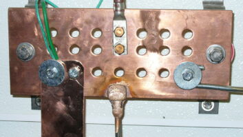
We spent two days disassembling the main FM35A and then replaced the grounding to the electrical panel with 10 feet of three-inch copper strap. The main service disconnect proved adequate, though we removed two disconnect switchers for the old transmitter, and replaced with single 250-amp breaker as the transmitter disconnect.
The FLX-40 offers a smaller footprint, close to half the size of its predecessor. The transmitter was delivered in an 18-wheeler to the gates of the power plant, which allowed us to coax the truck to the front door of the transmitter building. An immediate benefit was its modularity: Two tall, slender cabinets with dedicated 10 kW power blocks were delivered separately, along with a pump station and an outdoor heat exchanger. The pump station, responsible for transferring liquid from the transmitter to the heat exchanger outside, was situated in the same space as the old FM35A plate transformer.
For all the efficiencies gained from using liquid cooling at high power, there is a fair amount of planning and prep work when installing a new system. GatesAir supplied the pipes, hangers and valves required to transfer liquid from the transmitter to the outside. The coolant piping that comes out of the transmitter quickly rises to a high spot near the ceiling, and then slopes downward from there. This is necessary to ensure that the coolant flow is uninterrupted until it reaches the FLX pump module in the back-left corner.
The heat exchanger for the new cooling system is located outside.
Photo Credit: Brian Galante, President, Dimension PR

A contractor was hired to pour a concrete pad for the heat exchanger, outside the transmitter building where the pump sits. Flex line runs out of the building with a sweep downward, and we built a small wooden frame to support the liquid lines and electrical conduit. This conduit housed two three-phase lines that were run to the fan motors inside the heat exchanger, which each have separate, mounted disconnect switches to meet all electrical code requirements. From here, it was time to test the system.
As with the installation, the Radio Engineering Services team conducted all testing. Likening it to installing and testing a refrigeration system, there was a learning curve; this was the first liquid-cooled FM system the company has installed.
The system was first pressurized with approximately 15 pounds of nitrogen per square inch, and then left to rest overnight to ensure it held pressure, and the joints and fittings were sprayed with soapy water to confirm the absence of leaks. After tightening one loose fitting, the air was dispelled from the lines, distilled water was added, and the circulator pumps were turned on for testing. The water was drained after seven hours. This was an important step, as it removed all particles from the lines before adding the coolant.
A 40/60 antifreeze-to-water ratio was then added to the lines. (GatesAir supplied boxes of antifreeze along with support lines and fittings.) It then took several days to purge the remaining air from the system, which proved to be the most arduous part of the commissioning process.
Two air purge valves rest at the highest point of the system. It was a continuous practice of filling up, running the pumps and monitoring the pressure as the air was purged. As system pressure dropped, more coolant was added. This operation was performed four or five times before the system held to the recommended operating pressure of 18 pounds per square inch. Note this is not unusual for liquid-cooled system testing and is necessary to ensure optimal functionality.
The pump testing coincided with the transmitter testing. As the transmitter began to dissipate heat, the pump motors changed speeds to achieve the correct flow rate through rate of FLX-40�s power blocks. The flow rate fluctuates based on how much heat must be removed from the transmitter. The cooling fans within the heat exchanger also run at variable speeds based on how much heat requires removal from the heat transfer fluid. The FLX-40 is the heartbeat that keeps the system ticking, communicating changes in power block temperatures to pump module and heat exchanger.
While it�s too early to provide figures, there is little question that utility bills will be reduced based on lighter air conditioning requirements. The reduction in cooling loads will translate to lower electricity use, and WEBE expects to see those returns pick up as the months move on.
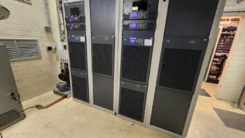
Two 10 kW power amps per rack make for efficient use of space.
Photo Credit: Brian Galante, President, Dimension PR

The FLX-40 design delivers other operational efficiencies, particularly when it comes to maintenance. The interior layout is highly modular, with all RF power modules and power supplied plugged into the front, along with a controller card that is accessible through the front door.
Each power amp � even the IPA � has its own power supply, ensuring nothing is overtaxed. These are capable of delivering 55 volts at 50 amps, a very tough design. These are hot-swappable modules and supplies that can be easily removed one at a time for testing or replacement without any discernable effect on signal quality and coverage. At the rear of the transmitter, each power block opens for access to the RF combiners, which is where the 10 kW from each of the four power blocks merge.
The FLX-40 integrates the GatesAir Flexiva exciter, essentially one of their low-power transmitters dialed way back. It is rugged and easy to configure, and stays locked into the right frequency. The only configuration required from our end was adding an IP address to enable remote monitoring.
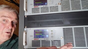
The FLX-40 also features a web interface. This is very useful, as it provides advance indication of potential faults and enables us to drill down several levels to look at liquid flow rates through the power blocks as well as performance and parameters associated with each RF module.
WEBE will soon update its Burk ARC16 monitor to an ARC Plus Touch to take better advantage of remote connectivity for transmitter readings.
For modulation monitoring, Cumulus has invested in the Belar FMCS-1, and Dave and his team carry the Belar units � including an FMHD-1 for stations with HD Radio.� His group and ours use them at transmitter sites and for remote monitoring via IP connections.
The FMCS-1 outlines parameters associated with the pilot, the RDS level and overall modulation with accuracy and detail. This is important for proper signal monitoring, and useful to ensure new installations are off on the right foot. For remote monitoring, it�s simple to hook up a cradle point and adjust the modulation and processing remotely while driving in the car. A glance at the GUI confirms the station is not exceeding FCC specs and achieving desired levels and RF performance.
Paul Thurst makes minor tweaks to WEBE�s Omnia 6 processor.
Photo Credit: Brian Galante, President, Dimension PR

To the point of remaining locked into frequency, the FLX-40 is delivering audio quality and requires no tuning. This is significant, as the previous transmitter often required PA tuning to achieve maximum bandwidth. As the bandwidth narrowed and hit the skirt, the transmission would experience some amount of synchronous AM, which created that �splattery� sound. The FLX-40 has a wide bandwidth, and generates little in the way of synchronous noise.
The installation will also support HD Radio when WEBE turns on their side channels. The FLX-40 will operate at �14 dBc,with a GatesAir FlexStar HDE-200 exporter inside the transmitter to accept main channel HD1 and analog signals from the Moseley StarLink. This unit also accepts multicast audio via the wireless LAN extension from the studio.
A FlexStar HDI-200 Importer is installed at the studio to multiplex program audio and data for the planned HD and HD3 channels. Since the FLX-40 can accommodate HD and FM together, we have transitioned to a low-level combining system far more efficient than the previous high-level combining system.
We experienced no startup issues with the FLX from the time we turned on the first 35 kW dummy load. It�s expected that the early efficiencies will quickly convert to a noticeable return on investment.
Dave Supplee of Cumulus Broadcasting and Peter Partineo of Radio Engineering Services contributed to this article.