111C Coils: A Golden Find
Aug 1, 2011 1:00 AM, By Doug Irwin, CPBE DRB AMD
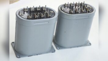
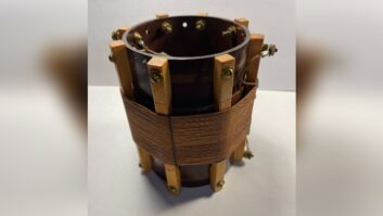
So while you were cleaning the storage area at the transmitter site, you found these things with solder terminals on top and a painted label that says 111C repeating coil (or something to that effect). What is it, you may ask? Don’t throw them out. After all, they officially belong to the telephone company, although they’ll never be claimed of course.
What you have is a valuable nugget.

Figure 1.
In the old days (before digital phone line circuits) if you needed to send audio to the transmitter site (as an STL) or somewhere else, you would order 8kHz or 15kHz lines from the telephone company. When the installer showed up at your facility, he stuck these transformers on the wall in your telecom closet. The line side windings were wired in series, and the drop side windings were wired in parallel. See Figure 1. This presented a 600 ohm termination to the equipment and sent the audio toward the nearest central office (CO) with a 150 ohms source impedance. This is because each winding will present a 300 ohms load (assuming each winding is terminated in 300 ohms).
These transformers are great little problem solvers to keep around. Here are just a few things that they can do.
Source isolation. I used to do a lot of remotes with stereo phone lines (in the days before ISDN) and I had a set of 111C coils mounted to a piece of pine with terminal blocks on the ins and outs. If I needed to isolate the source (like a front-of-house system) from the remote broadcast equipment, I would insert these in the lines from the stage. Nothing works better at killing ground loops than 111C coils. Both sides would be wired up for 600 ohms (Figure 2).

Figure 2.
– continued on page 2
111C Coils: A Golden Find
Aug 1, 2011 1:00 AM, By Doug Irwin, CPBE DRB AMD
Program distribution. You can use each winding separately of course; if you were to feed one winding with a 300 ohms source you would see that program repeated on each of the other three windings. It’s a good idea to make sure each winding is terminated in 300 ohms (Figure 3), otherwise the frequency response of the system may be aberrant. You could call this a poor man’s distribution amp (DA), but the fact of the matter is it works great, and it’s passive.

Figure 3.
Mono-Summing. You can mono sum with two of the windings, but make sure that you have the source impedance correct. Each winding needs to be fed with a 300 ohms source impedance. You may need to add build-out resistors in series with any DA or other output amps, otherwise the windings could compromise the peak output level of said output amps, creating a headroom problem. In addition, you need to make sure the phase relationship is correct between the left and right channel (unless maybe you want an L-R source?). See Figure 4. The two remaining windings will have L+R on them.

Figure 4.
RF isolation. One of the neatest things about the 111C coils is the built-in faraday shield between the line side and the drop side (see Figure 1 again). If you have a long line bringing analog audio to some location, say near an AM transmitter site, you can isolate that line from any amplifiers connected to the line side by connecting the S terminal to your local ground.
In this day and age of balanced AES digital circuits, Ethernet and fiber, the functionality given by the old trustworthy 111C coil isn’t nearly as important as it once was; however, one day it may save your bacon. Keep a couple on hand just in case.
Irwin is transmission systems supervisor for Clear Channel NYC and chief engineer of WKTU, New York. Contact him at [email protected].


