Clean up the Audio
Sep 1, 2008 12:00 PM, By Frank Foti

Audio coding has been around the professional sound industry since the early 1990s. Codec developers have been and continue to be on a fast track. Whereas the Motion Picture Experts Group (MPEG) once viewed audio quality to be excellent at 256kb/s and 128kb/s, it now offers the same judgment at much lower bit-rates. It’s much easier to improve the data payload, as compared to expanding the pipe.
To accomplish this requires using lower bit-rate codecs. Lowering the bit-rate increases potential degradation of audio performance. Advancement of codec design has allowed lower bit-rates to be employed, and most codecs sound decent at these rates, but they are much more fragile with regards to distortion and susceptible to artifacts. Due to the various types of codecs and lower bit-rates, getting a handle on the issues that annoy these functions is a moving target. The goal here is to seek out the gremlins and offer ways and means to avoid them.
All transmission systems suffer from some form of problem. The key to improving audio quality through a coded system is in locating the challenges and avoiding them. Take the FM stereo system � high frequency distortion and peak level overshoots were very common in early FM stereo generators. Both the pre-emphasis boost and sharp cutoff of the required low pass filters caused severe problems within the system. In-depth analysis of the system lead to the discovery of embedded pre-emphasis management and non-overshooting low-pass filters, which dramatically improved FM stereo performance.
While the concern for FM stereo was distortion and overshoot, coded audio suffers from sonic artifacts. These are the perceptible annoyances that bother the listener. Most sound anomalies are categorized as one form of distortion or another. Most common are harmonic distortion (THD) and intermodulation distortion (IMD). Coding artifacts are neither. When they are perceived, they occur due to inadequacies of the coding algorithm. Basically, this is the point where the encoder runs out of capability to reduce the audio data without the process of data reduction being heard. While there have not been specific technical terms assigned to describe these artifacts, they can be referred to as swishy-swirly, underwater-like, gurgle-like and sometimes synthetic-metallic.
Prior attempts
Dedicated audio processors that utilize look-ahead limiting and bandwidth control improve sound performance, but still do not reduce artifacts enough at low bit-rates, especially below 48kb/s. HD Radio, satcasters, podcasters and netcasters employ bit-rates at 24kb/s and lower. Reducing artifacts at these low rates usually requires severe bandwidth reduction, which in turn dulls the sound quality.
Careful listening to lower bit-rate coded audio reveals discoloration � not necessarily artifact-like or distorted, but some type of degrading ghost-like product being carried along with the signal. Attempts to remove it via signal processing seem to increase this characteristic. Listening to the output of the audio processor prior to the encode/decode section sounds very clean. Upon adding a codec to the scenario, the annoyance returns. This problem is observed with use of a common known codec for HD Radio (HDC) and various audio processors of different designers/companies. All produced the same results.
A clue to the problem is revealed when the timing in one of the audio processors is modified to reduce the amount of fast-limiting applied to presence and high frequencies. (This does not remove the limiting in this spectra, but changes the manner in which the limiter’s timing responds to transient signals.) The audio immediately opens, along with clarity in the presence and high frequency range.
Clean up the Audio
Sep 1, 2008 12:00 PM, By Frank Foti
Considering modification to the timing of the audio processor leads to a change in sound, thought was given to the effect of processor-induced IMD within the codec. The following simple test was crafted to observe the effects of IMD through a codec.

Figure 1. The test setup used to analyze low bit-rate audio.
Figure 1 illustrates the test setup. A multi-tone sinewave generator creates the source signals to stress the audio processor and codec. Frequencies were set to 400Hz and 11.5kHz. The output from the audio processor was routed in two directions � to the input of a multi-channel spectrum analyzer, and to the input of an HD Radio encoder. The encoder was routed directly to a corresponding decoder, and its output was connected to the other input of the spectrum analyzer.
The objective of this test was to observe whether or not any part of the dynamics function will generate distortion via the codec. The audio processor employed for the test was designed to condition audio in a coded environment. The back-end processing utilized look-ahead limiting in place of hard limiting/clipping. This reduced THD components in the codec and eliminated aliasing in the system. Tone bursts of the twin tones were used, as this would simulate the effects of transient activity in the source signal, as well as activate the fast-limiting functions in the audio processor.

Figure 2. A spectral display of the 400Hz and 11.5kHz tone bursts at the output of the audio processor.
Click image to enlarge.
Figure 2 is the spectral illustration of the tone bursts at the output of the audio processor. The twin-tones appear as would be expected. This is also the result when observed at the output of the codec when steady-state tones are passed through the processor and codec together.
Figure 3 illustrates the output of the codec’s decoder. Notice the significant spectra around the upper frequency of 11.5kHz. Further investigation of the situation revealed that the transient activity upset the encoder and caused added modulation in the upper frequency domain. This is what was causing the added ghost-like product heard prior. Is this possibly the effect of the SBR function becoming upset at transient information? This diagnosis is subject for a deeper discussion.

Figure 3. The output of the audio decoder.
Click image to enlarge.
The rigor of this test exhibited what appeared to be severe IMD in the signal. While broadcast source material does not contain transient twin-tones, it does contain plenty of dynamically transient signals within this frequency range. The extent of this added IMD is dependent upon the transients embedded in the source material. Additionally, fast-limiting time constants in the audio processor are capable of exaggerating, and/or creating this problem.
LoIMD
As with most discoveries, there’s an answer. In the above case, further study of the presence and high-frequency limiting algorithms yielded a method to reduce processor induced IMD. Utilizing a proprietary new function known as LoIMD, the algorithm is capable of providing fast-limiting to control transients, yet without agitating the encoder. When normal source content material is applied, the audio through the entire coded system is devoid of the ghost-like annoyances that were mentioned earlier.
The LoIMD function modifies the control function within a dynamics algorithm. Through internal analysis of the incoming dynamics, and IMD characteristics, the architecture of the control method is rearranged to provide a control signal that reduces, and sometimes eliminates IMD in the processed signal. The sonic result is cleaner sound for a given amount of gain control.
Clean up the Audio
Sep 1, 2008 12:00 PM, By Frank Foti
Headroom considerations
Another important factor regarding the coded system is headroom. Digital systems have an absolute maximum ceiling of 0dBfs. Theoretically, audio levels for transmission should be able to be set right up to this level. But, depending upon the encode/decode implementation, overshoots may occur. This is not consistent from codec to codec, but more so due to the implementation of the codec by various manufacturers. Additional input low-pass filters in the encoder may cause headroom difficulties. A well-designed encoder will ensure that any added input filter possess the same headroom as the system without generating overshoot that reduces headroom. Note: Most filter overshoot ranges from 2dB – 3dB, but can exceed this amount depending on filter characteristics.

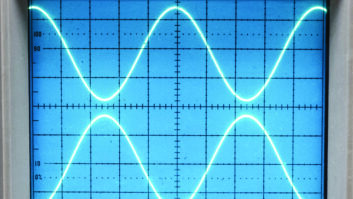
Figure 4. A 2kHz after clipping and being passed through a 15kHz low-pass filter.
Click image to enlarge.
It would be wise to test any codecs within a specified infrastructure to make sure that 0dBfs, is attainable without system overload or clipping. For this reason, setting the absolute peak level 2dB – 3dB below 0dBfs offers insurance to avoid clipping.
HD Radio has the capability to broadcast multiple content streams within the 96kb/s digital channel. Multicast requires the use of lower bit-rate audio coding. It is possible that extremely low bit-rate audio channels will exist, and require dynamics processing capable of consistent sound quality that yields low, or no sonic artifacts.
For those who wish to tweak on their own with existing processing equipment, the following should be observed:
- Avoid dense processing that contains fast limiting time constants. Try to reduce the attack time on functions when 5dB, or more, depth-of-compression is desired. This will reduce upper frequency processor induced IMD.
- Make sure the coding system provides full headroom. If the system clips on its own before 0dBfs, then reset the maximum input level to avoid system headroom problems.
- Low bit-rates will benefit from bandwidth control. A static low pass filter will reduce artifacts. The tradeoff will be perceived high frequencies vs. quality. A specialized processor for coded audio will offer some dynamic method to accomplish this.
- Do not use any final limiter that contains a clipper. The THD generated by the clipping function will cause more trouble than it’s worth. Precision peak control is needed in the coded system. As mentioned prior, specialized processing for this medium will provide a look-ahead limiter to accomplish this task. If these four steps are followed, improved coded audio will result.
Codecs and clipping
Sound media require peak control to avoid loss of headroom and eventual system distortion. Precision peak limiting accomplishes this. Hard limiting or peak clipping is used in conventional broadcasting, and it works quite well. The method does not technically degrade the system. (Overuse of final limiting is a subjective adjustment, and too much can degrade performance.) Suffice it to say that hard limiting does work as a precision peak controller within FM stereo and AM transmission.

Figure 5. The same clipped 2kHz audio display prior to the audio encoder/decoder.
Click image to enlarge.
The coded path offers a different set of challenges. It is not possible to overmodulate the system, as there is a precise peak ceiling of 0dBfs. Precision peak control is required, but the conventional method of clipping creates systemic problems, and those occur as aliasing products within the encoder. Figure 4 is an example of what happens to a 2kHz tone when clipped and 15kHz low pass filtered in a conventional audio processor used for FM stereo and passed through the HD Radio codec. This problem is consistent with other codecs too.
The cluster of energy that appears around 15kHz is aliasing components. These were caused by the 2kHz clipped signal from a conventional audio processor as the hard limited signal was routed to the codec. This is proof that all peak limiting for coded audio must use a limiting means that is void of THD content. Clipped waveforms are exceedingly high in THD. This is why the use of look-ahead limiting is the preferred mechanism for encoders. This style of limiter yields very low THD, and will not alias the system.
For reference purposes, Figure 5 is the same signal, prior to the codec. Notice how the odd harmonics line up as would be expected from a clipped waveform. The added strange content that appears around 15kHz in Figure 4 is what exaggerates coding artifacts when conventional style processing is applied to coded audio.
Research, testing, development and hopefully sound reasoning offered here now explain why coded audio performs as it does. Various signal processing and conditioning means can be used to bring life to coded sound. The test results illustrated here reveal that conventional compressors and limiters exaggerate artifacts. While signal processing, conditioning and peak limiting is required for coded audio, the processing must employ methods that do not contribute additional distortion aspects, as this is what degrades clarity and quality at low bit-rates, and sometimes even at moderate to higher rates.
Foti is president of Omnia Audio, Cleveland.
Clean up the Audio
Sep 1, 2008 12:00 PM, By Frank Foti
Process or not?
By Chriss Scherer, editor
You wouldn’t think of transmitting your station over the air without audio processing, but the same concept applies to an online stream. While competitive loudness isn’t the primary goal, compensating for variations in audio level and general level consistency are important concerns. Orban has assembled a comparison of audio clips using its Optimod-PC 1100 to show processed vs. unprocessed audio with various encoding formats.
www.orban.com/products/streaming/optimod-pc1100/audio_clips/
Resource Guide
Aphex Systems
818-767-2929
www.aphex.com
Audemat
305-249-3110
www.audemat.com
Broadcast warehouse
888-866-1671
www.broadcastwarehouse.com
Circuit Research Labs
480-403-8300
www.orban.com
Harris
800-622-0022
www.broadcast.harris.com
Inovonics
800-733-0552
www.inovon.com
Linear Acoustic
888-292-3117
www.linearacoustic.com
Neural Audio
425-814-3200
www.neuralaudio.com
Omnia Audio
216-241-3343
www.omniaaudio.com
Orban
480-403-8300
www.orban.com
TC Electronic
818-665-4900
www.tcelectronic.com
Translantech Sound
212-222-0330
www.translantech.com
Vorsis
252-638-7000
www.vorsis.com