How is your VSWR?
Sep 1, 2000 12:00 PM, John Battison
One phenomenon common to transmitter installations does not always receive the attention it warrants. Voltage standing wave ratio (VSWR) can wreak havoc in a transmitter when it suddenly increases and dumps the transmitter in the middle of the night.
The average AM transmitter is seldom prone to severe VSWR problems unless there has been a substantial change to the antenna tuning unit (ATU) or common point (CP) input tuning, or the transmission line is damaged. FM transmitters are just as susceptible to VSWR problems due to antenna problems or transmission line damage. It behooves the engineer to be aware of the VSWR and to ensure that antenna-system components are properly tuned for optimum VSWR.
VSWR facts of life A transmission line is considered to be a long series of inductances with parallel capacitors (as shown in Figure 1). Each pair of capacitors and inductors represents a very short piece of coaxial cable. Capacitance is produced by the spacing between the wires or inner and outer conductors in a coaxial cable. Inductance is determined by the size of the conductors. As current enters the line, it is retarded by the inductance of each tiny section. The consequent limiting of the charging rate of the capacitive element of the line determines the characteristic impedance of the line. The equation for characteristic impedance can be found in RF Engineering, June 2000, pg. 20. A rough approximation is given by the taking the square root of L/C, where L and C are per unit length of the line.
Another element in the antenna system is the effect of the dielectric in the coax on the speed of the signal. As a result, the signal travels more slowly through the cable than through the air. This difference may be as great as 65 percent. Thus, when the electrical lengths of transmission paths are important, it is essential to take velocity factor into consideration.
For efficient transmission of power, the load impedance must match that of the line and the generator. When these impedances match correctly, no power is reflected back along the line from the antenna to the generator and the only power lost in the system is that due to I superscript 2R losses and possibly some skin effect loss. But when the impedances do not match each other, losses occur and the power delivered to the antenna is less than that which enters the transmission line. If this occurs, the transmitter output will see either capacitative or inductive reactance. In such cases, the output stage would be detuned to an extent depending on the degree of mismatch. In severe cases it is possible for the final amplifier stage to be damaged.
When a line mismatch occurs, a standing wave caused by the reflected power appears on the coax. Every 180 degrees along the line major current and voltage points will occur. Obviously, halfway between each of these points minimum current and voltage points will occur. The voltage standing wave ratio is the ratio of V subscript max/V subscript min, measured at these points. The current standing wave ratio is the ratio between the I subscript max/I subscript min.
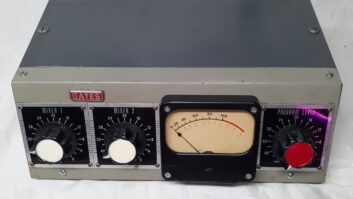
Measuring VSWR The basic VSWR meter consists of a line section with a short wire parallel to the inner conductor. The voltage developed on this wire is rectified and passed to a DC voltmeter, which is calibrated in terms of VSWR ratios. A value of 1.0 is shown at the minimum reading point on the scale and, as detected voltage increases, the meter goes upscale showing increases in the VSWR. In many FM transmitters, the output from this or a similar probe drives a PA breaker to protect the stage in the event of massive VSWR increases.
A VSWR reading of 1.1:1, or about 5 percent reflected signal, is usually the maximum that can be safely handled, although most situations are different. Remember that excessively high VSWR can cause high voltage breakdown of cables.
VSWR and AM antenna systems Most AM antenna systems use 50V transmission line but, regardless of line impedance, the same rules apply. AM transmission lines are often quite long, perhaps 300 feet or more, and carry comparatively low power in most instances. Line overheating due to high VSWR is rare. The operating frequency is low and the bandwidth of the signal is basically very narrow. Transmitter final stages are, in general, amenable to output load impedances of about 50V, although some modern transmitters are finicky regarding output loads. In many stations, it is unusual to find 50V Ohms j0 when an OIB is used to measure the line input impedance at the transmitter and at the ATU input. In many of these cases, measurement of line current showed a very small difference between the two ends of the transmission line, despite the apparent mismatch and expected high VSWR and corresponding power loss in the line.
In stations where a directional antenna is used, common point impedance is of great importance, but even there I have found more than a few stations with mismatches in CP and individual tower lines. Sometimes, checking RF power in the antenna has shown a discrepancy.
It appears that, in general, unless a finicky transmitter is used, reasonably high VSWR ratios can be tolerated in terms of RF radiation efficiency. But this definitely does not mean that such kinds of operation should be endured, nor are they up to the Standards of Good Engineering Practice.
VSWR and FM The average FM installation is far more susceptible to the effects of high VSWR. Again we find that 50V is the usual line impedance, and transmitters and antennas expect to see this value. VSWR by itself does not reduce signal coverage, but it can do nasty things to your signal.
Although not especially common in lower-power FM, operations discontinuities caused by transmission line coupling bullets and severely sharp bends in flexible lines can introduce VSWR effects and should be borne in mind. A number of problems can be linked to high VSWR. For example, stereo separation is affected. So is synchronous AM noise, and intermodulation products can increase.
Some antennas exhibit fairly narrow bandwidths. It is a good idea to check your operating bandwidth from time to time. If possible, the transmission system should exhibit flat response beyond the 200kHz spacing. If you don’t have the necessary equipment, you can use your FM transmitter and VSWR meter if your transmitter has an exciter with a variable frequency control adjustable in small increments.
Finally, extreme cases of high VSWR appear as hot spots on the transmission line. These cases lead to melted insulation and spacers, fire and off-air crises.