Installing a Directional Antenna
Jun 1, 2011 1:00 AM, By Doug Irwin, CPBE DRB AMD
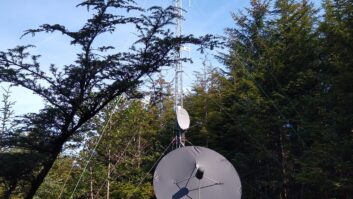
Perhaps you’ve had occasion (or will soon) to put up a directional antenna on a tower — say for example, an antenna for a translator or booster. Many times this type of antenna is an “array” made up of two antenna elements or more. The station’s construction permit will specify the bearing angles of the antenna elements, reference to true north. So before the day that the riggers are on the tower, looking down at you expecting an answer, you should consider just how to set this angle in the field.

Fortunately, with a few simple pieces of information, and some geometry, it can all be figured out ahead of time. The key piece of information is the relationship between the tower faces and true north. The tower owner should have that information from drawings when the tower was erected. A land surveyor will have included that information on the drawing. Take a look at Figure 1 to see what I mean. To make this example clear, I’ve set this tower so that the line BC goes directly east to west. Digging up your memories of geometry class, you can then see that the line BA is pointed at a bearing of 330 degrees true. Conversely, the line AB is pointed at a bearing of 150 degrees true. In this example, the antenna will be mounted on leg B, so I’m going to use the line AB as our reference bearing. Once that is clear to you, take a look at Figure 2.
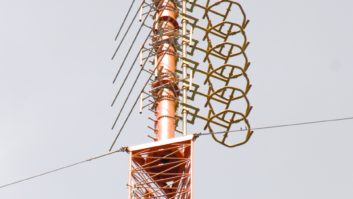
Now in figure 2 (not scaled by the way) I’ve depicted a horizontally polarized yagi attached to leg B.

Take a look at these two relationships:
Reference bearing – target bearing = remaining angle
180 – remaining angle = set angle.
Here is a quick example: Let’s specify the target bearing (taken from the CP) as 111 degrees. Then, from Figure 2 we have:
150 – 111 = 39 and 180 – 39 = 141 = set angle (with respect to tower face AB).

Of course I’ve made this a simple example by orienting the tower conveniently. Going back to Figure 1, the line AD is at a bearing 180 degrees true (and our reference angle is 150 degrees true). If, from drawings, you found that this angle is rotated clockwise (easterly) then simply add that clockwise rotation in degrees to the reference angle. If the line AD is rotated counterclockwise (westerly) then subtract that rotation from the reference angle. Once you have your reference angle, use the same two equations above.
So now you have your “set” angle. How do you get your riggers to implement it? Easy, actually. You’re going to create your own “wedge” (or pie slice if you prefer) with a piece of cardboard, a protractor, a straight-edge and a sharp knife. Take a look at Figure 3. Using a piece of stiff cardboard, and a protractor, mark the set angle, and then carefully remove the part of the cardboard that corresponds to the “remaining” angle. (You may want to consider cutting a semi-circular portion out of the center as well.)
Give this template to your riggers, and tell them to use it in setting the direction of the boom for the antenna that they’re pointing. (Refer to Figure 2 again.)
Irwin is transmission systems supervisor for Clear Channel NYC and chief engineer of WKTU, New York. Contact him at [email protected].
June 2011
The 2011 NAB Show in review, including the Pick Hits, Editor’s Picks, new products and Photo Blog; KTSC gets an upgrade; and Field Reports on the Blue Mikey and IK Multimedia iRig Mic….