Measuring Modulation
Oct 1, 2004 12:00 PM, By John Battison, P.E., technical editor, RF
The average textbook definition of modulation reads: modulation is a process in which the frequency, phase or amplitude of a carrier wave varies in step with the instantaneous value of the modulating signal. The closer the correlation between the modulating signal and the instantaneous value of the modulated carrier wave the better the quality of the eventual reproduction of the audio signal.
In the case of AM radio, the engineer is mainly interested in a complex audio signal consisting of music or voice frequencies, and the total width of the occupied frequency spectrum includes the carrier and sidebands. The higher the modulating frequencies the broader the bandwidth will be. Amplitude modulation produces only two side bands: carrier plus and minus the highest modulating frequencies.

No modulation (Figure 1a) and 100 percent modulation (1b) when viewed on an oscilloscope.
Sometimes the idea of AM power varying with modulation leads to misconceptions. The power of the actual RF carrier does not change with modulation. However, the total radiated power (carrier plus both side bands) with 100 percent modulation is 1.5 times the unmodulated carrier and the RMS current increases by the square root of 1.5 (1.225). At the peak of 100 percent modulation the instantaneous total RF power is four times the unmodulated carrier power. An inadequate or poorly regulated power supply can cause carrier shift at maximum modulation. Be sure that any repairs made to a transmitter power supply do not limit the peak available voltage and current.
Modulation generation
In its basic form FM modulation can be produced more simply than amplitude modulation. As its name implies, an FM signal is produced by varying the frequency of the RF signal at the rate of the audio signal. The carrier amplitude does not vary with modulation and modulation is usually performed in the oscillator stage at a low level. This simplifies the design of the intermediate RF amplifiers. FM transmitter bandwidth is directly proportional to the amplitude of the modulating audio signal, or in other words the percentage of modulation.
Distinctly different from amplitude modulation, frequency modulation produces an almost infinite number of side bands, requiring a wider bandwidth channel allocation that necessitates operation in the VHF spectrum. The FCC has allocated a total bandwidth of 200kHz per channel. The maximum frequency swing of +/-75kHz for 100 percent modulation leaves a 25kHz guard band on each side.
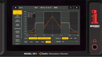
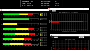
Measuring frequency-modulated signals is more difficult than for AM. In addition to reading simple modulation depth it is necessary to check such items as the 19kHz stereo pilot, SCAs and left and right channels. This means that a more complex instrument is needed.
IBOC digital transmission offers the promise of high-quality, error-free radio. Instrumentation for measuring modulation and transmission values is still in the development stage and several manufacturers are offering digital measuring equipment. Unfortunately, only insufficient information is immediately available for any in-depth presentation at this time.

Using the X-Y feed of audio vs. RF with no modulation (2a), near 100 percent modulation (2b) and overmodulation (2c).
The FCC has established required and maximum levels of modulation for radio stations. For AM, positive modulation must not exceed 125 percent and negative modulation must not exceed 100 percent. For FM stations, 100 percent modulation applies with small increases when subcarriers are added.
Modulation measuring equipment has been on the market for a long time, but there are times when a modulation monitor is not available or the monitor’s accuracy is in doubt. Amplitude modulation is measured using an oscilloscope. There are two simple methods of doing this, one measures the modulation envelope, the other method uses a trapezoidal pattern for measurement.
Monitoring modulation
The simplest method is to connect a pickup loop to the vertical deflection plates of the oscilloscope and set the horizontal sweep to a suitable frequency that will produce a stable modulation waveform picture. A stable audio tone is required for accurate measurement, and it is essential to ensure that the RF signal is stable. If the waveform is not stable it will be impossible make accurate measurements on the screen.
An easy way to obtain a display of the modulated envelope is to wind a pickup loop and connect it to the oscilloscope’s vertical input. Depending on the location of the oscilloscope, a short antenna with a tuned circuit may be used to tune the loop. The carrier with no modulation looks like Figure 1a. Figure 1b shows 100 percent modulation. Excessive overmodulation will cause a carrier shift.
The percentage of modulation is obtained from: modulation % = 100 x wave peak – wave trough
wave peak + wave trough
The units can be any suitable measurement.
The trapezoid method of measuring amplitude modulation is a little more complicated but seems to give more precise measurements. An RF pickup coil can be used, however using a short antenna for pickup may not be satisfactory because of random reflections.
A sample of the modulating audio signal is fed to the horizontal input of the oscilloscope. Then the amplitude of the audio
signal is adjusted to produce a usable trapezoid. In the absence of modulation, a single vertical block is produced like that in Figure 2a. As the modulation level increases, the length of the trapezoid’s left side decreases as shown in Figure 2b at near 100 percent modulation. The shape of the trapezoid should be symmetrical, and the top and bottom sides should be straight. Figure 2c shows overmodulation with an extended end and foreshortened trapezoid sides.
The calculation for modulation is similar with this plot, substituting B, the unmodulated value, for trough value and A for peak value. modulation % = 100 x A – B
A + B
E-mail Battison at[email protected].
Oscilloscope images courtesy of Broadcast Electronics.