New Life for Legacy Equipment
Dec 1, 2013 9:36 AM
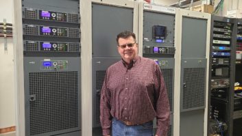
Burk ARC-16 I/O panels
As you likely know, the IP-8s were populated by single-pole, double throw relays with a common, a normally open, and a normally closed contact per relay (also known as a form-C relay). So, if you wanted to use the open-collector outputs from the Burk, along with its internal power supply, to make your own output panel you could do one of several things:
� Build your own array of form-C relays, or
� Take the opportunity to build an array of multiple-contact relays (such as a DPDT, 3PDT, 4PDT or more)
� Expand the number of open-collector outputs by using the Burk to drive further logic that has multiple, isolated outputs per relay. In other words, pressing channel 1 and raise (for example) actually provides multiple closures instead of just one.
� A combination of the above: an isolated relay contact (or more) that operates simultaneously with multiple logic outputs done via open-collector.
What about the analog inputs and status inputs, though? Well, these are easier to deal with. You’ll need to make up a cable to go from the DB37 on the ARC-16 to an external block of some type – whatever you prefer of course (see Figure 1.) I’m partial to the 25-pair Krone blocks. (Another favorite of mine is the ADC I-24, because you can mult on the front and back of it.) This might be the time to add two features as well: First, you know that the Burk analog input is limited to +5Vdc. Many of us have hung voltage dividers on the inputs to allow higher voltages to be read by the ARC-16. When setting up this block, to take the place of an IP-8, you could provision it to make the voltage dividers easier to install. Second, many of us have connected up parallel remote controls — sometimes diode isolation is necessary between the two units for the status inputs. Set up your new block to make diode isolation easy to do.

Basically I’m saying if you plan on making an ersatz IP-8, you should provision all the bells-and-whistles ahead of time.
Repurpose and reuse
A few months back I talked some about parting-out old equipment that you were keeping around the engineering shop. The idea was to compromise between hoarding too much junk and not throwing out something valuable, simply by gutting out the parts that actually had value. That at least will save space, right? So let’s take a look at a simple use of one of the items I picked – the RF relay.

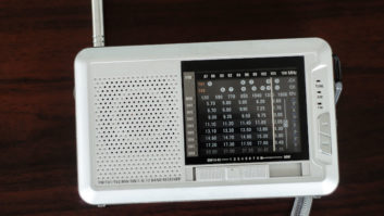
Figure 2
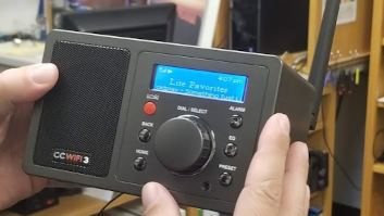
If you have two transmitters then likely you’ll want to listen to the local modulation monitor while it’s connected to the aux transmitter during testing. With an FM mod monitor you’ll likely need something that passes 100MHz easily enough. That is where your salvaged RF relay comes in to play. Most of those I’ve seen are SPDT, and you’ll need a power supply to energize the relay coil. One feed (likely your normally closed contact) will come from the main transmitter, and the other will come from your aux transmitter. Mount the relay on a rack panel, with buttons to energize the relay, and there you go. See Figures 2 and 3. Both construction projects by Jerry Burnham.

Figure 3
Irwin is RF engineer/project manager for Clear Channel Los Angeles. Contact him at [email protected].
December 2013
Interoperability standards for IP audio, a Seacrest Studio opens in Cincinnati, the FCC catches up on work, insight to HD Voice, and a rundown of portable recorders….