RF Combiners
Oct 1, 2001 12:00 PM, By Bob Surette
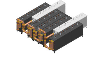
Transmitting several frequencies from a single broadband antenna system requires the use of a combining system, or combiner, composed of RF filters and interconnecting transmission line. Generally, a combiner can be categorized as branched (star point) or balanced (constant-impedance). These types may use band-reject (notch) or band-pass filters.
Components of combiners
There are several ideas to know when discussing combiners.
Tee or Star-Point Junctions. A tee junction, shown in Figure 1, is a coaxial component that provides for two RF signals to flow into a common path; a star-point junction is a tee with more than two input paths. This basic coaxial component is one of the building blocks of a branched combiner.
Figure 1. Tee junction schematic.

Filters. Filters sort RF frequencies, attenuating some while allowing others to pass readily. Depending on the design, a filter may either attenuate (band-reject type) or pass (band-pass type) a narrow bandwidth.
Frequency Response. Energy transfer through the band-pass filter is highest, or least attenuated, at the resonant frequency, and drops off at frequencies above and below that frequency. This frequency response is the fundamental property that enables a filter cavity to sort frequencies.
Group Delay. The signal takes a finite amount of time to pass through the cavity, and just as more energy is lost, so more time is taken at non-resonant frequencies. This is termed group delay difference, or group delay for short. Excessive group delay within the pass band results in signal distortion.
Figure 2. Branched combiner schematic.

Branched or Star Point Combiners. A branched combiner is a simple combination of a specially tuned tee or star point junction and the required number of filters to ensure a sufficient amount of isolation. For example, an FM branched combiner containing a three-cavity band-pass filter in series (Figure 2) may be used to provide the high-quality isolation required for two frequencies more than 1.6MHz apart.
The three-cavity filter system in Figure 2 is tuned for one of the channels in a two-station branched combiner and forms one leg of the combiner. The second leg is a similar combination of filters tuned for the other frequency. Figure 3 shows the basic combiner configuration.
TX1 and TX2 are the signals from transmitters 1 and 2 as they enter the combiner. The length of the coaxial line between each set of filters and the tee junction is adjusted to provide a high impedance (approaching an open circuit) to the other frequency, so that the power flow of each signal is through its own filter, out of the tee junction, and up to the antenna.
Balanced combiners
In a band-pass balanced combiner system, band-pass filters are used within the hybrid ring. The basic system layout is similar to that of a notch combiner.
Figure 3. Band-pass filter balanced combiner.

The power flow is shown in Figure 3. In the notch system, the filters reflect signal TX1 entering port 1. In the band-pass system TX1 also enters port 1, but passes through the hybrid ring’s band-pass filters and out port 4, while signal TX2, entering at port 3, is reflected by the filters and exits at port 4.
Bob Surette is manager of RF engineering of Shively Labs, Bridgton, ME.