Roll Your Own RF Filters
Feb 1, 2013 9:00 AM, By Doug Irwin, CPBE DRB AMD
In the November 2012 issue I wrote about combining FM antennas by way of filters. I received a question from a reader (Danny Wilson) about how to accomplish the same thing using transmission line filters. That can be done of course, and you’ll save some money by rolling your own.
To do this we make use of the transformer effect of transmission lines. Over one quarter wavelength, the impedance seen at the near end is opposite of that of the far end. More specifically: if you have an exact quarter-wave length of transmission line with an open circuit on one end, you’ll measure a short circuit on the opposite end. Conversely, if you short one end, you’ll measure an open circuit on the opposite end. Clearly this is frequency-dependent; I’ll show you the calculations shortly.
To do this we make use of the transformer effect of transmission lines. Over one quarter wavelength, the impedance seen at the near end is opposite of that of the far end. More specifically: if you have an exact quarter-wave length of transmission line with an open circuit one on end, you’ll measure a short circuit on the opposite end. Conversely, if you short one end, you’ll measure an open circuit on the opposite end. Clearly this is frequency-dependent; I’ll show you the calculations shortly.

Figure 1.
First we determine the wavelength of the desired frequency.
c/f = ?
c = speed of light
f = frequency
? = wavelength
Because we want to determine the 1/4?, and we’re working with megahertz and inches, we can simplify our equation to account for the multipliers and dividers and use 2952 for the constant of c. The resulting calculations for 100.3MHz:
2952/f = 2952/100.3 = 29.43″
Multiply the result by the velocity factor of the cable, which you can find online. One possible source is www.nr6ca.org/vf.html. As an example, RG-8 at 100.3MHz has a velocity factor of 0.66.
29.43 x 0.66 = 19.43″
This is the length of the inner conductor, so consider the length of the center pin of whatever connector you plan to use, and include that in the overall length.
– Next page: Notches for AM
Roll Your Own RF Filters
Feb 1, 2013 9:00 AM, By Doug Irwin, CPBE DRB AMD
Notches for AM
Another spot where a notch filter is often needed is in front of an AM receiver. It’s not uncommon to have a stronger, nearly adjacent AM carrier interfere with the desired signal in an EAS receiver. What can you do about that? One look at the formula for 1/4 wavelength in inches will tell you that using coax for this type of filter is impractical. You can still roll your own notch filter for the AM band though. Instead of using coax, we can use lumped constants otherwise known as simple capacitors and inductors. A quick search on the Web reveals at least one online resonance calculator (1728.org/resfreq.htm).
Another spot where a notch filter is often needed is in front of an AM receiver. It’s not uncommon to have a stronger, nearly adjacent AM carrier interfere with the desired signal in an EAS receiver. What can you do about that? One look at the formula for 1/4 wavelength in inches will tell you that using coax for this type of filter is impractical. You can still roll your own notch filter for the AM band though. Instead of using coax, we can use lumped constants otherwise known as simple capacitors and inductors. A quick search on the Web reveals at least one online resonance calculator (1728.org/resfreq.htm).
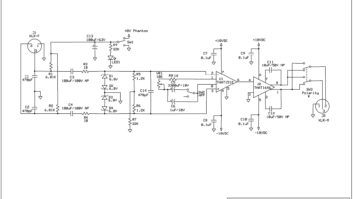
You’ll connect these components together in a series fashion, and literally connect it between the two input terminals on your AM receiver. See Figure 2. Alternatively, you could wire them in parallel, and then put that circuit in series with the input of the AM receiver.

Figure 2.
Put the components in a small metal project box, and connect the box itself for the ground reference of the radio receiver.
How will you tune up this filter? Connect the filter to the input of the receiver, and then tune the radio to the undesired frequency, and tune the filter for the weakest signal in to the receiver. Use your ears for this. Use care when tuning a small variable inductor like the one mentioned: you can easily break the slug in you aren’t careful.
Irwin is transmission systems supervisor for Clear Channel NYC and chief engineer of WKTU, New York. Contact him at [email protected].
We Need your tips
Tech tips may be suitable to earn SBE recertification credits. Send your tips to [email protected].
February 2013
KEZW goes green with solar power, safety in the workplace, audio editing software, World Radio Day and the UN, and the MXL BCC-1….
Reception Issues Resolved
Need to pick up multiple FM signal from different directions? Here are some methods that will capture weak signals….