Say goodbye to the weakest link
Jan 1, 2003 12:00 PM, By Steve Fluker

The old saying �You’re only as good as your weakest link� is true in almost everything, including the complete air chain of a radio station. A good side effect of consolidation is that it has brought us into the age of complete digital studios that provide features unheard of even as little as 10 years ago. Now that the FCC has accepted IBOC, we will see even more improvements as sites are updated with digital exciters and solid-state transmitters. With all of these advances in technology, don’t overlook what can become the weak link: the method used to get the audio from one location to another. This can be getting the program audio from the studio location to the tower site, or trying to get audio from a remote broadcast location back to the studio.
Look closely
I’ve had the opportunity to tour many radio stations and have been impressed by their new all-digital facilities, only to then walk into the rack room to find a more than 20-year-old STL system. While outlasting much of the other equipment speaks highly of the construction and design quality, these systems become the weakest link. All of the work involved in creating the perfect digital studio is lost if the digital audio is converted back to analog so it can be sent to the tower site.
One of the earliest introductions in the digital STL arena was developed by Dolby and is now available through Marti.

If you’re still running one of these old classics, it may be time to look into updating the system. While traditional, analog composite and discrete STL transmitter and receiver packages are readily available, and might be adequate in some cases, take the time to do the homework and fully explore the available options before buying the same old thing.
The basic digital upgrade
Digital STLs are not new. The first one hit the market more than a decade ago in the form of an add-on digital converter. These units are still available today and offer a way to convert an existing composite link to a 16-bit digital path without taking a hug bite out of the station’s capital budget. These simplex codecs are placed at each end of the signal path and will provide up to four 15kHz, 16-bit audio channels through a single data stream. The codecs use the composite ports of existing analog composite transmitters. This is accomplished with a moderate amount of data compression. In addition, the path will provide an RS-232 data path along side the audio. This port can be used for transmitter remote control, or to pass data to an RDS encoder at the tower site. While this add-on will help to reduce signal interference noises in the path, the data compression might produce undesired audible digital artifacts in the audio. To get the cleanest STL audio possible, look into replacing the entire system rather than just upgrading the existing equipment.
Linear choices
With the demand for higher quality came the release of the linear digital STL. With program audio coming from so many sources, it’s not possible to guarantee that the audio will always be linear. Satellite transmissions use data compression to fit more programming channels on the bird. Commercials received via the Internet have also been compressed, as are other sources such as Mini-Discs. While a single level of data compression is virtually unnoticeable, each time the signal passes through another compressed link, it will add to the audible artifacts. To keep the sound as pure as possible, it is best to use linear audio everywhere.
The uncompressed digital STLs deliver digital quality without the artifacts of audio coding.

This endeavor brought about the challenge to eliminate the data compression on the STL to a tower site, while still fitting within the bandwidth allocated in Part 74 of the FCC rules. To achieve this, the first of these units had to reduce the number of 15kHz channels from four to two, which is suitable for most FM applications. If additional audio channels are needed, there is enough spectrum remaining to add an optional single 12kHz channel or two 6kHz channels to this link. These additional audio paths are ideal for subcarrier audio. These systems also provide two RS-232 data ports for accessories.
While the two-channel STL is fine for most applications, there was still a demand for more 15kHz channels for companies consolidating not only their studio locations, but also their transmitter sites. Through the use of quadrature amplitude modulation, creative engineers have been able to achieve four linear 15kHz audio channels over a single 950MHz link. This is great in areas where this STL band is crowded. You can also use a system like this to save money on your equipment needs. Rather than purchasing redundant transmitters and receivers for two radio stations, you can simply buy one system per station, using the auxiliary channels as the back up.
Location, location, location
Placing the audio processor at the studio has long been preferred, mainly for creature comforts. It allows a quieter listening environment and places the processing in a more convenient location for the program director. Most digital STL systems deliver only discrete left and right channels to the tower site, requiring the installation of a stereo generator at the transmitter site. This can be done in more than one way. Perhaps the easiest solution is to upgrade to a digital exciter with a built-in digital stereo generator. The AES-3 digital audio output of the STL is connected directly to the input of the exciter, resulting in a totally digital air chain. If this isn’t an option, or if the backup transmitter still has an analog exciter, install a digital STL with an optional stereo generator installed in the STL receiver. This offers the feel of a traditional composite link that interfaces directly to the exciter. In these receivers, the digital and composite outputs are active at the same time, making it easy to feed two transmitters at once. Pay close attention to where the pre-emphasis curve is generated, however. Some of these stereo generators do not have the pre-emphasis option, and the engineer has to select it in the processor at the studio.
Quadrature amplitude modulation has made it possible to send four linear digital audio channels over conventional STL paths and frequency spacings.

If you don’t want to give up the composite STL, a new one was introduced last year that offers a full 16-bit composite digital link in the standard 950MHz band. This allows him the full processing adjustments, including pilot injection from the studio end.
Planning for IBOC
With the FCC’s acceptance of IBOC, the attempt to keep the processor at the studio may become a moot point. The IBOC/HD Radio exciter needs a linear unprocessed audio signal at its input. It then provides an output to feed to the main carrier audio processor and a second output to feed an IBOC audio processor. Because this new exciter must be at the tower site, the user will be forced to move the processor out of the studio. Fortunately, most new processors offer RS-232 port options and software to adjust them via a PC from any remote location.
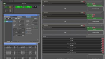
Figure 1. T-1 systems provide a great deal of bandwidth to use for more than just program and contributed audio.

A second issue with IBOC is the ability to transmit audio bandwidths up to 20kHz. The standard composite and digital STLs pass 15kHz, although we are now seeing some manufacturers addressing this issue.
The RPU is still alive
The typical STL system is only a one-way path. It will channel audio and data from your studio to your tower site, but it cannot get anything back. If you try to use the RS-232 ports, you can send data out, but you can’t get the return information needed for things such as remote monitoring and metering of the transmitter. In the past, it was common to use a narrow band 450MHz data channel or even a dial up telephone line to return the data.
Another need for a return link is for remote broadcasts. While many remotes are now being handled by ISDN and POTS audio codecs, there are still those times when it’s necessary to use a RPU system. RPUs are still valuable for the one-time-only broadcast when it doesn’t make sense to pay the money to install a telephone line. They are also convenient for broadcasts from outside locations such as parks or beaches, or other areas where it isn’t possible to easily install a telephone line. Low power, portable transmitters are also a great way to get audio out of a large building, such as a shopping mall, convention center or even a courtroom where it can be received by a remote vehicle that can then repeat the signal back to the studio. While their use has decreased, the RPU will still be around in some capacity for many years to come.
When used with a V.35 codec, the Moseley Aries 400S provides a digital link in the RPU band.

To get a better coverage area for an RPU system, many stations locate the receiver at the tower site to gain the extra height for the antenna. This leaves the challenge of getting the audio back to the studio, though. Typically a repeater is used to relay the audio back to the studio site, but this ties up more channels and provides yet an additional area prone to interference.
The next level
If a station’s needs include a data return channel or RPU repeaters, consider looking at a bi-directional STL system. These typically come in the form of a rack mount chassis with a variety of plug-in modules to customize the system to an individual’s needs. There are several choices in audio cards alone, and the user can send audio channels in either direction, and choose bandwidths ranging from 7.5kHz to 20kHz. The user can select analog or AES-3 digital inputs, and choose to stay linear or incorporate data compression if more audio channels are needed. One possible configuration might be to use a high-quality linear audio module to send the program audio to the tower site, and use multiple lower bandwidth audio channels to return the RPU audio channels back to the studio. Include a 15kHz return link to the studio and install a back-up satellite dish and receiver at the tower site for emergencies.
Be creative with the system, too. Add a LAN module and take a computer to the tower site. This will allow direct access to the office network files, e-mail and Internet access without monthly connection fees. Every engineer has taken a trip to the tower site, only to get a call from the sales or business office with a computer problem the second he walks into the transmitter building. Now he can log on and take care of problems without driving back to the studio. Connect a camera to the PC and send security video over the Internet connection to monitor the site from anywhere. RS-232 and RS-422 ports can be added, which work bi-directionally and offer a solid connection to the transmitter remote control system or to talk to an RDS encoder. When IBOC forces the station to relocate the audio processing to the tower sites, use these data ports to adjust the audio from the PC on a desk in the office.
To save money on monthly expenses, add a telco module to the chassis, then install an extension on the office PBX system at the tower site. Calls can be directly transferred from the receptionist to the tower site. Install another extension to add a fax machine at the tower site and take advantage of the group long distance rates that the office receives. Eliminate telephone service at the transmitter site, which might be important for towers in remote locations where telephone service might not otherwise be available. Figure 1 shows just how versatile these types of systems can be.
Avoiding T-1 costs
The downside to these bi-directional STL systems is that they won’t operate on a standard 950MHz channel allocation. The most common method is to use a T-1 phone line to connect the two ends. Unfortunately, the monthly fees for these lines could make this idea cost prohibitive. In some locations, a remote tower site may not have telephone service available.
There is an answer to this problem. Data and audio multiplexers can be connected together via a spread spectrum RF link. These are available in two bands, a 2.4GHz band, which gives the equivalent bandwidth of a single T-1 line, or in a 5.8GHz band, which will double that capacity to the equivalent of two T-1 circuits. Because these channels are not licensed, it is in the station’s best interest to do whatever is possible to protect the station from interference. Use a high gain, highly directional antenna and install it as high as necessary for a clear line-of-sight path, but not any higher. These antennas are so tight that they can operate at distances as far as 30 miles with excellent rejection of other signals. Spread spectrum is being used successfully in many locations across the country, however if you still are concerned about interference, keep the old 950MHz STL channel in operation as a backup link to the tower.
With IBOC on the way, think ahead and make choices wisely. While a bi-directional system may look expensive, consider all of the other components it will be replacing and it is really a bargain.
Fluker is director of engineering for the Cox Radio stations in Orlando.