The self-resonant folded unipole antenna: Measured Results
Oct 1, 2000 12:00 PM, Sylvio M. Damiani
An article in the October 1999 issue of BE Radio described the design of the self-resonant antenna for use with medium-wave or long-wave broadcasting. At that time, I disclosed only a theoretical method of obtaining a self-resonant antenna. This is a purely resistive antenna with no input reactance and an extremely wide bandwidth – features that are useful for AM broadcasting. The first measurements have confirmed the predicted characteristics and some extra features were discovered as well. These features have a natural application in IBOC DAB and should make the transmission system as transparent as the studio equipment.
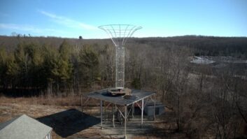
Several small AM stations (1kW typically) in Brazil installed a self-resonant folded unipole like the one described in the October 1999 issue. ZYK-767, a 1kW station on 1490kHz, and ZYK-563, a 1kW station on 850kHz, are using a self-resonant folded unipole antenna right now. Over the past year, some low-power stations including ZYK-548 in Araras in the state of Sao Paulo, and some medium-powered stations like Radio Alvorada, a 5kW station in Londrina in the state of Parana, also have used a self-resonant unipole antenna. In addition, some high-power stations, including 50kW ZYK-688 on 1260kHz in Sao Paulo City, are now using a self-resonant unipole antenna with excellent results.
High-power ZYK-688 uses a two-tower array. The present version is a self-resonant folded unipole used as antenna one and a simple monopole as antenna two, which operates as a parasitic element on the array. The parasitic element is base-loaded with a variable vacuum capacitor to adjust phase. The base current ratio is less than 1:1, which produces a radiation pattern that has two medium nulls with the major lobe toward Sao Paulo.
Calculations and measurements The antenna performance results for station ZYK-688, the 50kW on 1260 kHz in Sao Paulo, are shown in Table 1. Note that the measured values are sensibly better than the calculated values. The measured values were used to calculate an optimized TEE network to match the 50V coax cable to the system. Table 2 shows the ATU impedance curve data.
To my knowledge, this is the first time that a medium-wave directional antenna array (two-tower antenna in this case) was measured to show such a wide operating bandwidth. The results of 20 kHz referenced to the carrier frequency are quite impressive. A phase-locked loop RF generator was used in place of the transmitter’s oscillator for the frequency sweep impedance measurements.
Notice that the transmitter accepted the frequency variation across the entire frequency sweep. There were no overload problems noticed during the work, even when measured at 20kHz from the center carrier. This means that the loads presented to the transmitter final stage were acceptable, even at 20 kHz. This also demonstrates that frequencies 20kHz from the carrier were passed without any attenuation in the final stage.
Figure 1 shows the symmetry of the SWR plot around the carrier frequency. The low values at these points denote the superior bandwidth of the array using a self-resonant folded unipole antenna as the main radiator.
For IBOC, system linearity and symmetry will be critical (see Implementing IBOC, page 30). Plans are in place to report the results of another medium-wave self-resonant folded unipole antenna installation as an omnidirectional radiator.