The Vertical Radiator: How it Works
Sep 1, 2013 8:00 AM, By Jeremy Ruck, PE
At the heart of the transmission of every radio signal is the antenna, and the simplest construct is the dipole. So basic is the dipole antenna that the half-wave version is in nearly all circumstances used as the reference point for other antennas. In those instances where the dipole is not used as the reference, its cousin the theoretical isotropic radiator is used instead.
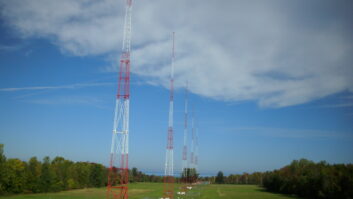
The vertical radiator, as its name implies, is a metallic mass, usually a tower in the broadcasting world, beginning at an elevation close to ground level and extending vertically to some height. This element is excited in certain fashions, with the series and the shunt topologies being the most common. If the half-wave dipole is the standard by which most other antennae are compared, then the reference point for vertical antennas is the quarter-wave vertical.
Frequency multiplied by wavelength is equivalent to the velocity of light, which results in an inversely proportional relationship between the two quantities. Thus, when either frequency or wavelength is increased, the other must decrease so that the product of the two remains equivalent to the speed of light. Therefore, wavelength will vary depending on dial location.
Thinking big
At FM, a quarter-wavelength varies by about six inches across the 20MHz span of the band. In the AM band, however, a quarter-wavelength ranges from a little less than 145′ at 1700kHz up to a whopping 464′ at 530kHz. So theoretically speaking, your 464′ of steel on 530kHz will perform identically to the guys down the road on 1700kHz with only 145′ of tower. Two such facilities for a given power level will, of course, have vastly different footprints, but those variances have to do with other factors, which we will discuss at a later date.
You may hear your consulting engineer refer to tower heights and spacings in terms of degrees. Indeed closer examination of Commission-issued licenses and construction permits also use that notation. Remember that a radio wave propagating is a sine wave, which is a repetitive oscillation, and can be thought of as a circle. Rotating through 360 degrees on a circle will bring you back to start. So a quarter-wavelength is one-fourth of a circle or 90 degrees, a half-wavelength 180 degrees, and so forth.
The distribution of current in a vertical radiator generally follows a sine wave, or sinusoidal, distribution. For theoretical vertical antennas, the maximum current point falls 90 degrees below the top of the tower, while in practice it will not occur that far down due to the velocity of propagation, which increases with tower cross-section. The voltage in the tower tends to follow a cosine distribution, which is in essence a sine wave shifted by 90 degrees. Thus, the maximum current location corresponds to the minimum voltage location. This variation in current distribution allows for steering of the radiation in a vertical plane, and is one of the techniques used to achieve allocation compliance with DA designs.

Figure 1. Theoretical current and voltage distribution on a vertical radiator. Click image to enlarge.
Keep current
The current in the antenna is of course a very important quantity to us as broadcast engineers. For the non-directional station the product of the base current squared and the resistance component of the tower impedance yields the antenna input power. This is the genesis of the I2R term that is bantered about, and comes from an application of Ohm’s Law nestled within an application of Joule’s first law. Joule’s first law says power is voltage times current, and by Ohm’s Law voltage is current times resistance, thus power is current multiplied by itself with that product multiplied by the resistance.
Pondering this a little deeper, it should be clear that if the voltage and current in the tower varies by height, and resistance, or more correctly impedance, is the quotient of the voltage and current in the antenna, then the impedance of the tower will vary by height as well. Indeed this is the case, and every radiator will have its own characteristic impedance. Theoretically speaking, a generic quarter-wave tower will have a base resistance of around 37O and zero reactance, assuming a perfectly conducting ground system. In reality, however, the ground system does not conduct perfectly, which combined with other localized factors, skews the impedance from this value in practice. As the radiator height varies from this point, the impedance will of course fluctuate. Shorter towers will tend to result in lower impedance values, while the converse will of course be true for taller elements.
Although the impedance of the tower may vary somewhat between its inactive and active states, much larger changes will occur when the radiator is an element in a directional array. When an array is active, the elements mutually couple based on the current ratios and phase shifts in the elements combined with the array geometry, yielding a set of drive point impedances. In some arrays the geometry and ratios create conditions where the impedance of one or more of the towers is negative in magnitude. Many engineers tend to have a visceral reaction to a “negative tower”, and may even contemplate acquiring garlic to be part of their wardrobe, or carrying silver ammunition. The negative tower simply delivers power back into the phasor rather than having power delivered to it from the phasor, and is a somewhat common occurrence. Instability in arrays with negative towers, usually the cause of disparaging comments, tends to more often than not be a function of the proximity of the impedance to zero ohms rather than the sign of the impedance.
Either way, the impedance of the radiator will never fall nicely on the characteristic value of the line or the design value for the transmitter. This is where the antenna tuning unit (ATU) or antenna coupling unit (ACU), your preference, comes into play. This device is a network of passive components that transforms the impedance of the transmission line to the impedance of the tower with a particular phase shift. The components used to create these networks are capacitors and inductors, as their theoretical power dissipation is zero watts.
An increase in the height of the element will also tend to increase the efficiency of the radiator, but only up to a certain point. The efficiency of the radiator is the unattenuated field strength that it will generate at some distance. Historically the mile was used as that distance, but currently the Commission uses the kilometer as that standard. Up to around 190 degrees or so in height (0.53 wavelength), the field strength from the antenna will increase. Above this point, the field strength at ground level will continue to increase at a lower rate, and a high angle lobe at 60 to 70 degrees above horizontal crops up. Above about 5/8 wavelength or 225 degrees, the high angle lobe increases at a greater rate, and the radiated field strength at low angles, which is necessary for local coverage, drops off rapidly. That pesky sine wave pops up yet again.
The vertical radiator is most definitely a time-tested concept that has served us as broadcasters extremely well over the years. Even in these days of ubiquitous computing power and information accessibility, there is still a certain mystique associated with them. I guess ultimately that is a good thing as it continues, at least in some small way, the promotion of the romanticism that is radio.
Ruck is the principal engineer of Jeremy Ruck and Associates, Canton, IL.
September 2013
Digital test devices, Red River Radio rebuilds, vertical radiators explained, Field Report on the Tieline Merlin Plus, Z100 celebrates 30 years and more….


