Towering Over Wyoming
Dec 1, 2008 12:00 PM, By Charles Dozier

The state of Wyoming is famous for its diverse geography. The mountainous terrain of the western half of the state contrasts sharply with the high-altitude prairie region of the easternmost areas. Near the eastern city of Gillette, the unusual surface features pose distinct challenges for building new transmission facilities. The terrain, climate and other environmental factors all play decisive roles in the planning and execution of the project.
Legend Communications, which operates 14 radio stations in Wyoming, recently added two new stations to its Basin Radio Network in Gillette: KAML-FM, upgraded from a C1 station at 96.9 to a C0 at 97.3, and KDDV-FM. The Basin Radio Network serves the Gillette market and beyond in the eastern part of the state, known for its flat landscape, clay-like ground surface and generally arid climate.
With these factors in play, locating the ideal site to erect a tower was an effort. The absence of mountains made it difficult to pinpoint a location with enough height to reach the outer edges of the listening area. The closest sites with suitable heights were too far east or west to cover the market.
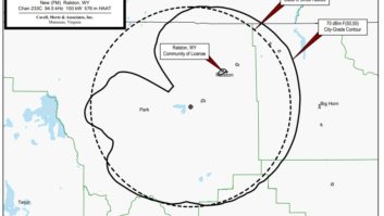
After much consideration, a plot on private land with access to three-phase power was secured 15 miles from Gillette. The flat topography required a tower that is the tallest man-made structure in Wyoming. The 1,153′ ERI tower features a single combined antenna that emanates separate FM signals from two Harris HT30 transmitters. The transmitters, featuring Harris Digit exciters, went online in October, each broadcasting at 25kW to local audiences. The height study, conducted by consulting engineer Jeff Brock, confirmed each station would reach the entire market. Harris provided the complete transmission package outside of the tower for both stations.
The initial tower specification called for a height between 1,200′ to 1,300′ to accommodate two dedicated antennas. The weight of the second antenna and associated transmission line would adversely affect structural balances, driving the expense of the project up. The switch to a single combined antenna eliminated the cost of the added support.
Building steel
Rocky Mountain Erection, a structural steel firm based in Yukon, OK, installed the foundation for the tower and raised the structure. After initial engineering studies to evaluate the ground structure, the RME team was brought on-site to drill holes, remove rock and anchor the base. The flat terrain collects water easily, so the project was scheduled around the rainier months to ensure a work environment relatively free of mud and poor weather conditions.

The tower foundation being laid.

Towering Over Wyoming
Dec 1, 2008 12:00 PM, By Charles Dozier

The building is set into place.
Prior to pouring the concrete, our engineering team ran a 4″ copper strap under ground to bring up over the lip of the tower base. This provided a deep grounding system for electrical safety, along with an ERI Mag Rod for extra protection.
The main tower stands at approximately 1,050′, with a pair of giant plates with 2″ thick solid steel meeting near the apex. The final 100′ or so comprise the ERI Lambda mounting section, a free-standing segment with a 3′ sway in either direction for wind resistance. Giant bolts connect tower lights and a 10-bay ERI antenna to the Lambda mounting surface.
The ERI SHPX antenna is a 10-bay design, providing plenty of gain to hit a 100kW ERP without requiring larger transmitters. The Lambda section can be rotated, which allowed us to point the antenna in the direction that best matched our desired output pattern. The bottom bay of the antenna sits at approximately 1,040′ to maintain a consistent output pattern and distance. Radomes were added to the antenna to prevent ice accumulation.
Local considerations
Eastern Wyoming is in the middle of a construction boom, and finding a contractor to build a new transmitter facility in a remote location proved impossible. We contracted with Thermo Bond of Elk Point, SD, to deliver a pre-built, customized building to house the transmitters.
Following approval of the design, the shelter arrived fully assembled with lights, electrical layouts, grounding systems and HVAC ventilation, among other attributes. Thermo Bond shipped the building by truck from South Dakota, and it was lifted off the truck using a crane and set on the concrete pad. The building was pre-inspected and included all the required electrical drops for the Harris HT30 transmitters, which simplified installation. A quarter-inch steel plate was also added to the roof for ice protection, and electrical was run into the building off the nearby three-phase transformer.

The Thermo Bond building was prewired and ready for equipment.

Towering Over Wyoming
Dec 1, 2008 12:00 PM, By Charles Dozier

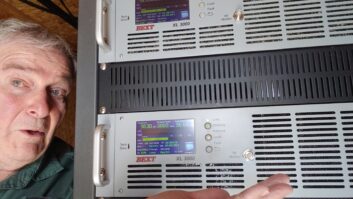
Transmitters in place and running
Most of the 16′ � 28′ interior space is reserved for the Harris HT30 transmitters. The transmitters were part of the greater Harris turnkey package, which also included the ERI high-power FM antenna and combining system, a Moseley PCL 6020 STL package, an Omnia 3-FM audio processor (installed at the studio), Andrew transmission line, Myat RF plumbing and connectors, and Bird RF monitoring equipment.
Harris performed a thorough set up of the HT30 transmitters at its facility in Quincy, IL. According to our computers, the transmitters were sharply tuned to frequency and underwent 24 hours of test runs at the facility. Reassembly at the transmission site was simple, requiring basic interconnections between the high voltage systems and main cabinets before installing the tubes and enabling the remote control system. The engineering team currently uses Burk Auto Pilot remote dial-up units to access readings from the transmitters and alert us of unusual status readings. The point-to-point Burk units communicate over subcarrier cards connected to the legacy phone system.
The Harris Digit exciters were set up at the factory to determine the amount of power needed at each station’s frequency to drive the IPA modules. We like the fact that the new HT30 design eliminates a driver module that formerly bridged the exciter and IPA. The removal of that stage means the exciter compensates for the 15W to 20W of drive power that is missing now that the exciter runs straight to the IPA. But the benefits include simplification of the transmitter design and maintenance, and the purging of occasional matching problems that sometimes affected the gain.

Stacking the tower sections.
The combiner integration was more challenging. The transmission equipment was delivered with a host of 3″ hard line and extra elbows from Andrew. This equipment was used to build trombones that would address the signal matching delays at the combiner. The trombones added length to the line through a series of loops, which ERI engineers cut to size on-site to synchronize everything. Our chief engineer, Tony Kyriss, used a band saw to cut cleanly through the hard line, and the swivel points in the elbows made the plumbing assembly less complicated.
Towering Over Wyoming
Dec 1, 2008 12:00 PM, By Charles Dozier

Hoisting the transmission line up the tower.
Most of the 16′ � 28′ interior space is reserved for the Harris HT30 transmitters. The transmitters were part of the greater Harris turnkey package, which also included the ERI high-power FM antenna and combining system, a Moseley PCL 6020 STL package, an Omnia 3-FM audio processor (installed at the studio), Andrew transmission line, Myat RF plumbing and connectors, and Bird RF monitoring equipment.
Harris performed a thorough set up of the HT30 transmitters at its facility in Quincy, IL. According to our computers, the transmitters were sharply tuned to frequency and underwent 24 hours of test runs at the facility. Reassembly at the transmission site was simple, requiring basic interconnections between the high voltage systems and main cabinets before installing the tubes and enabling the remote control system. The engineering team currently uses Burk Auto Pilot remote dial-up units to access readings from the transmitters and alert us of unusual status readings. The point-to-point Burk units communicate over subcarrier cards connected to the legacy phone system.
The Harris Digit exciters were set up at the factory to determine the amount of power needed at each station’s frequency to drive the IPA modules. We like the fact that the new HT30 design eliminates a driver module that formerly bridged the exciter and IPA. The removal of that stage means the exciter compensates for the 15W to 20W of drive power that is missing now that the exciter runs straight to the IPA. But the benefits include simplification of the transmitter design and maintenance, and the purging of occasional matching problems that sometimes affected the gain.
The combiner integration was more challenging. The transmission equipment was delivered with a host of 3″ hard line and extra elbows from Andrew. This equipment was used to build trombones that would address the signal matching delays at the combiner. The trombones added length to the line through a series of loops, which ERI engineers cut to size on-site to synchronize everything. Our chief engineer, Tony Kyriss, used a band saw to cut cleanly through the hard line, and the swivel points in the elbows made the plumbing assembly less complicated.
The combiner feeds into 4″ transmission line to the outside and up the tower. We initially looked at 5″ line because of concern that the 60kW capacity of the 4″ line was cutting it close. The tradeoff was a much lower weight load on the tower and easier line management. ERI ran the line up the tower to the antenna, and looped it in an orderly manner back to the ground. Bird watt meters at the combiner output monitor signal strength out of the combiner and up the transmission line.
The Moseley STL platform provides fixed 950kHz RF transport over two hops. The STL path from the studio is different from the norm, if not unique. Legend Communications also operates KGWY-FM in Gillette, approximately 1,000′ across the street from the KAML-KDDV studios. The KGWY studio site has a 500′ tower essentially in its backyard, and it is the STL receive site for the first hop.
Towering Over Wyoming
Dec 1, 2008 12:00 PM, By Charles Dozier
The downtown tower location is ideal for providing low-power signals to a portion of the market in the event power is lost at the main KAML-KDDV transmission site, which currently lacks a generator. A Moseley STL antenna and receiver was installed at the KGWY transmission facility to support the first hop and establish the backup, low-power transmission. From KGWY, the Moseley system transports the KAML-KDDV audio another 15 miles to the main transmission site, where a receiver sits inside the building.
The Moseley STL system is frequency agile, and a backup system sits on a nearby shelf in the event of a failure in the main receiver. Spare HT30 parts share the same limited storage space, with a nearby workbench for maintenance. The Thermo Bond shelter contains and protects this equipment, but the building is nearly at full capacity with little room for new equipment.
The Thermo Bond shelter offers plenty of other benefits though, notably in terms of HVAC design. Although six tons of AC cooling are available in the building, the eastern Wyoming climate is cool enough to limit AC needs to the thick of summer. Thermo Bond installed ventilation to exhaust hot air out of the transmitters and to the outside at each side of the building. When AC is not required in the cooler months, consumer-grade swamp coolers draw in cool air from the outside. In the winter months, the swamp coolers are on thermostats and shut down when the building is cold, as do the exhaust fans over the transmitters. This allows heat to remain in the building when outside temperatures drop as low as 30 degrees below zero.
Final prep
The final step before firing the transmitters was tuning the antenna. ERI made one final trip out to the site, measuring the feed off the antenna with a spectrum analyzer and inserting slugs around the appropriate conductors to achieve proper tuning. KDDV required more adjustments due to an undesirable level of reflected power, but by trial and error, the levels were adjusted appropriately until we were satisfied.
Legend Communications is looking ahead to potential HD Radio installations. The use of a single combined antenna and 4″ transmission line for the two analog transmissions minimized the weight today, allowing plenty of load capacity on the tower for two separate antennas and line feeds for HD Radio transmissions tomorrow.
Dozier is director of engineering for Legend Communications and is based in Cody, WY.
Equipment List
Andrew 4″ Heliax, ?” Heliax, dehydrator, Super Flex jumpers, transmission line hardware, wall feed-thru panel
Bird Wattcher
Burk ARC-16, Auto Pilot
ERI SHPX diplexed antenna with radomes, FM combiner, Lambda mount, Mag Rod, transmission line hardware, tower
Harris HT-30, Digit
Mark 4′ STL antenna
Moseley PCL 6020, STL/RPU power divider
Myat rigid transmission line
Omnia 3-FM-Turbo
Scioto 4″ copper strap
Thermo Bond building