Vertical Radiators
Nov 1, 2008 12:00 PM, By John Battison, P.E., technical editor, RF
Broadcasting owes its existence to the works of Maxwell, Faraday, Volta, Ampere, Hertz and several other 18th century scientists. Their combined research showed us the way to develop today’s broadcast system. Most of these men knew each other or were familiar with each other’s work. In fact there was a certain amount of rivalry between them. In the days when this rivalry existed, an unknown friend with poetic talent published the following poem in Paris.
Around the magnet, Faraday is sure that Volta’s lightnings play,
But how to get them from the wire?
Ah! Take a lesson from the heart
�Tis when we meet, �tis when we part
Breaks forth the �lectric fire!
Whoever this person was, he knew that breaking a circuit produced a spark!
From the fundamental laws developed by these scientists we have learned how to generate, control and direct electromagnetic radiation, which is the heart of broadcasting today. However, sometimes we tend to forget some of the fundamental facts of electronic life involving radiation which, after all, are requisite for radio transmission. We talk about half-wave or quarter-wave radiators, their radiating characteristics and radiation efficiency, and it’s quite easy to lose track of what we mean sometimes.
Maxwell developed two main equations that apply to most of our RF and audio broadcast operations in one way or another. He said a changing electric field will produce a magnetic field and vice versa. This is virtually the secret of broadcast radiation. The changing RF current in the AM antenna produces a magnetic field in the area around the antenna. This in turn develops an electric field, which leads to another magnetic field and this phenomenon propagates itself through space. This apparently simple relationship leads to the creation of radio’s essential induction and radiation fields.
One field, now called the induction field, is very important immediately around the antenna. It consists of lines of force set up by the current and voltage in the antenna and contains only reactive energy because the two fields are 90 degrees out of phase. This field diminishes quickly and is approximately equal to the inverse square of the distance. Very close to the antenna the induction field is extremely strong and may induce very high currents or voltages in adjacent conductors. It is sometimes the cause of excessive interference immediately adjacent to a radio transmitter.
The field that we, as radio engineers, are interested in is the radiation field. It consists of an electromagnetic wave composed of lines of force that have become detached from the antenna. This field contains real power; both electric and magnetic fields are in phase and power is taken from the antenna and carried by this field. Its intensity is inversely proportional to distance and it diminishes far less rapidly than the induction field. Less than about a half wavelength from the radiator the two fields are equal. From here on the radiation field predominates and is vitally important for communication purposes.
For comparison purposes when discussing antenna efficiency it became necessary to establish a standard comparison value point at a fixed distance. The strength of a radio signal is measured in terms of the intensity of the electric field. It is the voltage developed in a wire 1 meter long in the parallel field of the signal. It is expressed in terms of volts per meter. Originally, a distance of 1 mile from the antenna was chosen. However, several years ago with the attempted national conversion to the metric system, the FCC decided to use kilometers in place of miles when comparing antenna. We presently seem to use a combination of metric and standard distance measurements, which can lead to errors if care is not used. I prefer to use miles rather than kilometers.
Vertical Radiators
Nov 1, 2008 12:00 PM, By John Battison, P.E., technical editor, RF
More power
One of the most important units in a radio transmitter engineer’s daily life is antenna current. This is the measure of the RF current flowing in the antenna. Power is important to the station owner and he always wants more power. The only way to get more power is to increase the antenna current with a given antenna resistance. Without resistance no power is developed. The equation P = I2 Rant calculates the antenna power where I is the antenna base current, or the common point current in the case of a DA.
Rant is the measured antenna or common point resistance, which includes ground system losses. The correct all-inclusive term is radiation resistance. It is commonly referred to as base resistance because that is the place where it is measured. Reference was made to base resistance, the proper term is base impedance because an antenna has inductive or capacitive reactance in addition to its very important resistance.
The most generally used broadcast antenna is the vertical radiator. Although it is commonly called a quarter-wave antenna, it is often several degrees plus or minus a quarter-wave in height. Sinusoidal current distribution is usually assumed and used in most antenna. However, occasionally measured antenna current distribution is required by the FCC in the case of unusual configurations.
An actual quarter-wave antenna will have approximately 37O base resistance and zero ohms reactance on its operating frequency. Immediate surroundings, as well as tower width, can have an effect on the base impedance.

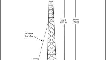
Figure 1. The current distribution across a 90-degree radiator decreases along the height of the structure.
The single 90-degree radiator actually operates with an imaginary 90-degree radiator below the surface completely separated from it. Figure 1 shows the current distribution at the base of the tower.
The important measure of a transmitter is its field strength at one mile. A 180 degree dipole has a resistance of approximately 73O. With 1 amp, two quarter-waves each with half the radiation resistance with 1 amp of RF will produce the same field strength, i.e. 37.4 mV/m. The power required is I2 R or 1�1 �37 = 37W.
If RF power is doubled, the field strength at a given point will increase by the square root of two. In other words, field strength increases by the square root of the power increase.
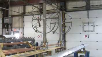
In order to match the tower’s operating impedance to the 50O transmission line, an antenna tuning unit (ATU) is required. This is a network that transforms the 37O operating resistance to 50O and matches the j0 of the line and the measured antenna reactance. An L or a tee network may be used. I prefer a tee because it gives easier control of the match in my opinion, and this is often very important when tuning a directional antenna.
E-mail Battison at[email protected].