Before reading this article, read and consider the question shown in the box.
Society of Broadcast Engineers certification is the emblem of professionalism in broadcast engineering. To help you get in the certification exam frame of mind, Radio World Engineering Extra poses a typical question in each edition. Although similar in style and content to exam questions, these are not from past exams nor will they be on any future exams in this exact form.
CBRE Sample QuestionAn RF static drain coil is used where and for what purpose in your radio station?
a. An important device in any switching supply. Actually an LC circuit, it allows the shunting to ground of the HV back spike when the current stored in the main switching inductor is liberated on turn off.
b. The proprietary curlicue spikes normally on top of a tower to drain static buildup.
c. A high-impedance coil usually attached from the antenna input to ground to drain off static charges caused mainly by lightning or wind-driven dust.
d. The small inductive value (normally built in to the tube socket) between the input and screen grids in a VHF power tube to avoid internal arcing.
e. The near-mandatory conductive rug that you should be standing on whenever you work on CMOS circuitry to avoid device destruction.
The best ideas are the simple ones that solve a larger problem with elemental elegance, and the static drain coil is an excellent example of this maxim.
The correct answer is c.
The problem we have before us is to attenuate in intensity the static charges, either around the tower before a discharge or after high voltage is induced into the system when lightning strikes, and in unique cases where a static charge build-up is developed by wind driven dust or sand. Serious damage can result if the discharge or strike is large enough and finds an errant path to ground through your transmission plant.
The static drain coil is but one element of the system that accomplishes this attenuation. At a minimum, three components are present: the arc gap, the tower grounding and the static drain coil. These components are integrated into the antenna of a typical AM station and its antenna matching system, which is essentially a high-frequency AC network power matching scheme.
The ATU part of that system was discussed previously (“Are You Ready for the SBE Exam?” in the Feb. 20 issue) as the way to match the transmitter to the ether for maximum power transfer. The usual connection for the static drain coil in a series AM antenna is between the ATU output and the antenna input, with the arc gap essentially in parallel with the coil.

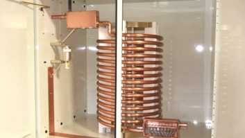
Fig. 1: Fried static coil In practice, this static drain device can be either a high-impedance resistor (non-inductive 100k Ω, 200 watt is the industry standard) or a coil with high reactance. The latter is more common. The other end of the coil or resistor is solidly connected to the antenna ground system right at the base of the tower. The static drain functions as a dissipation path to ground, keeping lightning and static charges out of the antenna tuning system.
Inductive reactance increases with frequency (inductive reactance = 2*p*ƒL, where ƒ is the frequency and L is the inductance). Inductive reactance impedes the flow of AC current and, as you can see from the above formula, the impedance grows larger with frequency. This concept is the key to how the static drain coil works and survives.
In the case of the coil, an inductance is selected such that at your operating frequency its reactance is so high that virtually all of the power from the transmitter flows through the ATU and into the antenna; in effect the static coil appears to be an open circuit at radio frequencies. However, the DC resistance of the coil to ground is just a few ohms.

Fig. 2: Fried static coils Static charges are close to DC in frequency and drain down to ground through the low reactance (near DC resistance value) of the coil. To help this process, a series capacitor is usually the last component in the ATU to prevent any DC from flowing backwards from the antenna into the ATU.
As a practical matter, the design of the inductive static drain is usually a 2 or 3 inch diameter coil with more than 100 turns of #20 or so size solid wire. This wire cannot mechanically support itself so a coil form of some type is used. The RF at the point of connection can be in the neighborhood of 1000 volts (or higher if the base impedance is very high), so the coil winds at the top are more widely spaced to avoid arcing between winds. The spacing is progressively less as the potential diminishes towards ground.
Obviously # 20 wire cannot withstand the large sustained current flow of a lightning strike so the companion device, the arc gap, is used to pass the large current to ground of a direct strike.
The physics works like this: The arc on the gap occurs when it is forced to do so by the high impedance that the lightning “sees” at the static coil. The very fast-rising wave of the initial component of the lightning strike acts as a high-frequency impulse, creating high impedance to any current flow through the coil. This forces the energy to the arc gap and with the resultant arc most of the energy in the strike is dissipated to ground … we hope.

As the intensity diminishes the frequency drops, lowering the impedance of the coil and theoretically allowing a current flow that the coil can handle. There is little defense for the strikes in the “grand mal” variety and the coil may open (like a fuse) from the excessive energy that dissipates everywhere and anywhere it can (see Figs. 1 and 2). For this reason, most antenna maintenance schedules should include a DC check of the coil to make certain the coil is continuous (has continuity to ground) and still functional.
Although many antenna systems depend on the ground screen to take those lightning strikes to ground, experience indicates that an additional lightning ground grid made up of at least four ground rods driven vertically into the ground around the base of the tower, in something like a 20 ft diameter circle and connected directly to the ATU, minimizes the dissipation distance and overall damage from a significant strike.
For an overview of the care and maintenance of your static drain along with the rest of the components around it, visit John Bisset’s 2000 Workbench article at radioworld.com/reference-room/workbench/rr-workbench52.shtml
A CBT question for next time: “In the schematic, what component or components sets the amplifier stage gain?”
a. The gain is set by the chip itself and can be obtained from the IC flysheet.
b. The gain is set by VCC, as the higher the supply voltage the higher the gain.
c. By the value of R3, as this resistor to ground sets the offset bias seen by the op amp, hence the gain.
d. By the value of R2, as this resistor sets up a voltage divider with the very small input resistance of the op amp and thus the feedback level.
e. R1 and R2, as they create a voltage divider setting the feedback level and thus the gain.