One of the things that attracted me to the broadcast engineering field is that when solutions are not commercially available — and sometimes even when they are — broadcast engineers often design, build and install their own.
I picked up on this on in my first radio job while changing automation tapes at an FM station, doing news and running the board for baseball play-by-play. Throughout the facility at the AM/FM combo (and yes, the AM was the headliner in those days) were gadgets designed and built by the chief engineer. From time to time, I would walk by the engineering shop and see the chief looking down through a cloud of solder smoke at some gizmo he was creating on the workbench. It was fascinating!
Perhaps the thing that really got my interest was that the gizmos were of such good quality. They weren’t junk, built out of spare parts in plastic Archer project boxes (Radio Shack’s brand was Archer in those days, remember?). Instead, they were professionally constructed devices that looked factory-built, durable enough to stand up to the abuse handed out by DJs.
Since those early days of my career, I have built a lot of gizmos. The first was a means of starting and stopping turntables using the remote start pushbuttons on the front of a Collins IC-10 on-air board in the first station where I held the title of chief engineer. I remember that I used latching relays to do the trick. The DJs appreciated the new functionality, since they didn’t have to feel around blindly for the toggle on the turntable to start it while they were reading copy or whatever, running the very real risk of bumping something and knocking the record out of cue.
That early success started an almost 40-year run of such creations, some of them home runs and some strikeouts, but I learned that sometimes, if you want a device that does something out of the ordinary, you have to build it yourself. I also learned that sometimes you can build something yourself at a fraction of the cost of a commercially available product.
HOW TO TRAP AN AM
Sitting at a desk most of the time these days, I don’t get much opportunity for gadget building anymore; but recently I had the opportunity to design and build two such projects. In the process, I learned a few things that you might find useful.
Our company Crawford Broadcasting recently purchased an AM station in San Diego. Our intent is to operate it primarily as an extension of the brand of our Los Angeles area 50 kW powerhouse; that means that it will largely operate unattended. We will feed the station with a satellite signal from our Costa Mesa studios, but we will have to comply with FCC EAS rules, placing an EAS unit in line at the transmitter site to forward RMTs, alerts and activations automatically.
That sounds easy enough, but in San Diego, the LP-1 and LP-2 stations are both AMs, and we would have to receive and demodulate those signals from a diplexed AM site from which two other AMs transmit. It would take a heck of a receiver to pull in those two LP signals in the presence of the very high fields of the two AM stations at the site.
With that in mind, I knew I needed a trap of some sort, some device that would give me a notch of 20–30 dB (or more) on the frequencies of the two local stations while not excessively attenuating the rest of the AM band.
I didn’t exactly start out on a cocktail napkin, but I did sketch out a two-frequency trap/filter network on a piece of scratch paper, and I worked out all the ideal component values. Now the challenge was to convert that sketch into a real-world device using real-world parts.
JUST A FEW PARTS
My first stop was at www.mouser.com, always a good place to start when looking for electronic components of all kinds, though certainly not the only such source. I found the inductors I would need and some compression-type ceramic/mica variable capacitors. I also found a cast aluminum project box, a copper-clad circuit board, mounting hardware and BNC jacks.
For a few dollars — less than $50 — I soon had all the pieces on hand and was ready to go to work.
Rather than going to the trouble to print a circuit board for this single device, I simply marked out the large pads I would need on the board. I then used a Dremel to remove the copper in thin lines around the pads and traces. There weren’t many in this device, so it wasn’t a lot of work. I then soldered the components into place, mounted the board in the cast box, installed the BNC jacks and soldered them to the board.
About three minutes with the network analyzer and I had what I needed, a relatively flat passband with two deep notches on the frequencies of the two local stations. I affixed Kroy labels to the three jacks (antenna input and two receiver outputs) and shipped the box to San Diego. Our chief engineer installed it there and it worked like a hose. We have clean, clear reception of the two LP stations with no degradation or de-sense from the local AMs.
By the way, the advent of label makers from P-Touch, Kroy and others has done wonders for DIYers. No more dry transfer lettering that comes off, no more clear nail polish to try and seal the transfers. We can now create custom, professional labeling for our home-brew gizmos.
LIGHT MONITORS
Shortly after that, I ran into another issue, one that stations are running into all over the U.S.

Fig. 1: It’s not quite a “cocktail napkin” drawing, but the schematic of the breadboard circuit was scratched out in pencil on a notepad. It is difficult if not impossible to monitor the operation of LED tower lights properly from the primary side of an Austin transformer on an AM tower. Hysteresis currents in the Austin mask the tiny current changes that result from the beacons going on and off. The only solution is to monitor directly, right on the wire that feeds the beacons on the tower. The challenge, then, is coupling the indication from the on-tower monitor across the base insulator.
I had run into this problem at our new 50 kW AM facility in Los Angeles a couple of years ago; the solution then was a pair of commercial fiber optic devices at each tower, purchased at considerable cost. When the problem arose at one of our stations in Michigan, I cringed at the thought of spending the better part of $1,000 per tower to couple the tower light alarm indication across the base insulators of the four towers in the Detroit directional array. It occurred to me that I might build something myself for a lot less.
Once again, my first stop was www.mouser.com, where I searched for fiber optic transmitter and receiver devices. I found quite a few, but ended up zeroing in on some devices made by Avago Technologies. For $12 apiece or thereabouts, I ordered two of each to experiment with, along with a supply of 2 mm fiber optic cable.
When the parts arrived, I used a breadboard that I had bought for my daughter when she was going through broadcast engineering school, to build up and test the devices. In short order, I found that these devices were exactly what I would need.

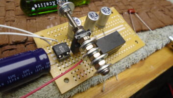
Fig. 2: Express PCB’s design tool makes creating your own custom printed circuit boards a snap. Since I would be dealing with a binary signal that would either be on or off, the external components would be few: just an opto-isolator, a couple of resistors, some LED indicators to help with troubleshooting and some decoupling capacitors.
I breadboarded all that up in just a few minutes, sketching out the schematic on a notepad as I went (Fig. 1). After some testing and playing around with resistor values to achieve the desired device currents, I had to turn it into a real-world device.
FROM PROTOTYPE TO QUANTITY BUILD
I knew that if we were going to build up a batch of these things, we would want printed circuit boards. Thankfully, www.expresspcb.com had what I needed. With their free software app, I was quickly able to lay out a board that would be either a transmitter or a receiver, depending on which side of the board is populated with parts (see Fig. 2). Most of the cost of the PCBs was in the initial layout, so I had a sizeable batch run. Total cost was about $200 for 20 boards. The etched, drilled and plated boards arrived within a week.

Fig. 3: The finished fiber-optic devices. The unit on the bottom is the transmitter. Both use an identical PC board with different holes populated. The LEDs indicate input and output signals. Back at www.mouser.com, I ordered a batch of the fiber optic transmitters and receivers, resistors, capacitors, opto-isolators, headers and Phoenix connectors. When those parts arrived, I quickly built up a transmit/receive pair of the devices and tested them. They, too, worked like a hose. Now we have a supply of these devices with which we can couple the output of an SSAC or other LED tower light monitor across a tower base insulator for about $50 per tower! An assembled pair is shown in Fig. 3.
REWARD YOURSELF
All this is to say that in our plug-and-play industry, there are times when “do it yourself” is the way to go. With great online suppliers and tools, engineers can develop and produce the custom devices they need quickly with little effort and expense. In going the DIY route, you can often provide your employer with significant savings, but you will also have the satisfaction that only comes with producing something unique with your own hands.
W.C. “Cris” Alexander is director of engineering at Crawford Broadcasting Co.
Share your DIY success stories with us. Email [email protected].