Faraday’s coil confirmed the connection between magnetism and electricity. This image, found on WikiMedia Commons, was originally published in Frederick Bedell’s “The Principles of the Transformer” (1896). In this fourth article in our series (radioworld.com/fundamentals) of occasional articles about electronic components and formulas that have been critical to the development of radio, we focus on inductance and how that electrical property was discovered.
By 1820, when a young Danish physicist named Hans Christian Oersted was experimenting with electricity and magnetism, much was known about those two phenomena, but nothing was known about the interaction between them.
Magnetic compasses and lodestone had been around for centuries.
Pieter van Musschenbroek, Ben Franklin and others had experimented decades earlier with bottled up electricity (literally bottled up in van Musschenbroek’s invention, the Leyden Jar), but no one understood the connection between the two.
Oertsed’s experiment used a galvanic cell (a battery) to send current through a wire that passed just above a magnetic compass. When current flowed through the wire, the compass needle deflected from north momentarily, but returned almost immediately. When Oersted removed the voltage, the needle momentarily deflected in the opposite direction! Clear evidence that electricity and magnetism were somehow connected, but the key word was “somehow.”
He did not have that worked out, and in fact, it would be a few more years until Michael Faraday and lesser-known American scientist Joseph Henry figured out the answer.
LINES OF FORCE
Faraday and Henry, working independently of one another, showed that, as current from a battery flows through a wire, a momentary current would flow in a second, nearby wire.
Still, like the compass needle in Oersted’s experiment, current in the nearby wire only flowed momentarily when voltage was applied, even if the voltage was left on. This was a mystery.
Faraday was the one who finally worked that out in 1831, when he wrapped a ring of iron with two independent coils of wire on opposite sides of the ring. Voltage applied to the “primary” winding induced a momentary current flow in the secondary winding. He called this device, appropriately enough, an inductor, and hypothesized that the momentary current flow in the secondary winding was due to waves of some sort, radiating outward from one coil to the other through the iron core.
He was correct, and we know the peaks of those waves as magnetic “lines of force” that emanate from poles of a magnet, as well as from the windings of an inductor.
Faraday’s iron ring and its coiled windings was actually a toroidal transformer, which not only validated Oersted’s experiment but also led to the discovery of mutual inductance, which makes transformers possible.
Both Faraday and Henry were instrumental in working out the properties of electromagnetism, and the existence of EMF, or electromotive force, but since the international value assigned to capacitance had already been named after Faraday (in truncated form: the farad), the unit for inductance was named the henry.
In any event, Faraday showed that it was the expansion and subsequent collapsing of the magnetic “lines of force” cutting through the secondary windings as voltage was applied and removed that caused the secondary current. That realization, in turn, explained the momentary nature of the current, as well as the reason it changed directions as the primary voltage was removed. His experiments and formulas that confirm the results became the basis for the Law of Induction, which bears his name.
CLICK AND CLACK
With radio’s emergence several decades in the future, the first inductors were used primarily as electromagnets.
But in a prescient moment, Joseph Henry soon realized that the principle of using an electrical current to create a magnetic field might be of great value beyond those simple devices. To that end, he designed a very sensitive electromechanical device that “clicked” every time a pulse was received over a pair of wires.
Samuel F.B. Morse immediately adapted it to his coded system of dots and dashes, and the telegraph was born.
Henry also invented an offshoot: the electrical relay. He mechanically linked a set of electrical contacts to a spring-loaded lever and placed the lever over a coil. When he applied power to the coil, the ferrous core magnetized, attracting the lever, which in turn pulled the set of contacts to make them touch a second set of stationary contacts, completing an electrical circuit.
These applications all used DC power, just as did the first experiments with capacitance.
When DC power is applied across a coil, it resists current flow as the magnetic lines of force “use” the current to expand. Once fully expanded, however, the lines of force need essentially no power to stay that way. When the power is removed, the lines of force collapse, giving back the energy that was absorbed when they expanded in the first place (but in the opposite direction as originally applied voltage). If current flow in an inductor is initially at zero when voltage is applied, then according to Ohm’s Law, the coil’s resistance is infinite and the voltage across it is maximum.
But as the lines of force fully expand and stabilize, current flow correspondingly increases to maximum, at which point the coil’s resistance to current flow is limited to no more than the resistance of the wire, which is typically very low. In that state, Ohm’s Law says that the voltage drop across the inductor is minimum (although it is not zero, owing to the resistance of the wire itself).
As we found out last time (in the Oct. 22 issue), capacitors work exactly opposite, with current at maximum and resistance (and therefore voltage), at minimum as voltage is first applied. AC is different from DC, since it continuously cycles from positive to negative and back again, and inductors, just like capacitors, continuously react to that change voltage. The difference is in the way they react.
ELI THE ICE MAN
All beginning electrical engineering students are taught to remember this difference in the two types of components by the mnemonic ELI the ICE man, which makes use of the engineering symbols for voltage (E), inductors (L), current (I) and capacitance (C). E Leads I (ELI) in an Inductor, and I Leads E in a Capacitor (ICE).
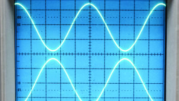
As it turns out, when AC voltage is applied, these “phase differences” are 90 degrees in both components, so when inductors and capacitors are combined in a circuit, the phase difference can add to 180 degrees (completely out of phase) or can subtract, to be in-phase. This is the key to the operation of tuned circuits, as we shall see in a future article.
The formula for inductive reactance is
XL= 2πfL
Where XL is inductive reactance in ohms, π is 3.14; f is the frequency of the applied voltage in hertz, and L is the inductance in henrys.
From this formula, it can be seen that as either frequency or inductance, or both increases, inductive reactance (which is nothing more than resistance to AC current) will increase as well. Another way of saying this is that inductors are low pass filters; they pass DC voltages but resist AC voltages, particularly higher frequency voltages like those found in broadcast transmitter RF amplifiers.
For this reason, some inductors are called RF chokes, since they “choke” the flow of RF current. This resistance to high frequencies is the exact opposite of a capacitor, where the reactance decreases as either frequency or capacitance increases.
For any given size of capacitance, then, capacitive reactance is inversely proportional to frequency. At the same time, for any given value of inductance, inductive reactance is directly proportional to frequency. With these two properties in mind, it is easy to see that we can calculate values for a capacitor and inductor so that they each exhibit the exact same reactance to some specific frequency of AC voltage. In that situation, the capacitor and the inductor can be used to create a tuned circuit and that is what we’ll take a look at next time.
Jim Withers is the owner of KYRK(FM) in Corpus Christi, Texas, and a longtime RW contributor. He has four decades of broadcast engineering experience at radio and television stations around the country.

