Noel Maginnity is a consultant in Carterton, New Zealand.
An alternative audio program input is often required at a medium-wave transmission site. During STL maintenance or if the STL fails, it is always good to have something on-air, even if it may not carry the correct commercials. Dead air loses listeners. The alternative source can be provided with the use of an “off-air” receiver tuned to another station of the same network.
However, the difference between the local (transmitter) signal levels and the distant station signal level can be substantial; around 80 dB (or even more) could be expected. Most receivers cannot tolerate excessive, off-channel, signals. It is therefore necessary to filter the strong local signals out of the receiver input. The Medium-Wave Bandpass Filter was developed to overcome these problems.
A bandpass filter provides a more satisfactory solution than the use of bandstop, or notch, filters. The bandpass filter rejects everything but the wanted frequency. Unwanted frequencies include transmitter harmonics, and intermodulation products, especially when there is more than one transmitter at the site.
Radio and TV broadcasting in the 1980s here was run by the Broadcasting Corporation of New Zealand (BCNZ), a government corporation. There were several radio networks, and two TV networks throughout the country, originating out of Wellington. At that time, there were also a few privately owned radio stations in the main population centers. I was a technician/engineer responsible for the maintenance and operation of various transmitter sites in the Waikato, as a staff member of the BCNZ.
During this era, off-air receivers were part of the equipment line up at a typical transmitter site in New Zealand. Tuned loop antennas showed some promise, but were difficult to install and always susceptible to picking up power line hash. A vertical whip antenna gave promising results. Various matching methods were experimented with, ending up with a toroid inductor.
Any antenna at a transmitter site is going to collect a significant amount of RF from the on-site transmitter(s). I developed the MW Bandpass Filter as an in-house project to get some useful performance results with the available receivers from the vertical antenna.
FILTER DESIGN
With many hours and lots of mathematics, one can come up with a good filter design. The Bandpass Filter evolved from an idea that required some experimentation. Several versions were constructed and results measured. They all showed better results than the original, so that is how the specifications were derived. Here are the design goals for the filter:
Impedance 50 ohms Insertion loss 2.5 dB Bandwidth, −0.5 dB 20 kHz Selectivity, −40 dB 250 kHz Dimensions 180mm x 180mm x 100mm

Fig. 1: Three-section tuned MW Bandpass Filter schematic diagram. The filter is based on three LC series tuned circuits (see Fig. 1). The input and output tuned circuits are grounded inductive coils. This provides the means to couple the radio frequency signal into and out of the filter via tapping points on the two outer inductors along with accurate impedance matching. Each circuit is tuned to resonance at the pass frequency by adjusting C1a, C3a and C5a. A signal generator set to the pass frequency and a field strength meter and 50-ohm load will enable an accurate adjustment to be made.
The bandwidth is determined by the amount of coupling between each circuit; slight over-coupling is used in this filter, and it is set by the capacitance to ground. Over-coupling of tuned circuits results in a greater bandwidth; the full 20 kHz is passed resulting in no side-band losses. The three sections of the filter are each contained in their own shielded compartments, and the coupling is determined by the use of feed-through capacitors, C2 and C4, and some additional parallel capacitors. If less bandwidth is needed, it is possible to experiment with more fixed capacitance across C2 and C4, as this will reduce the coupling between the three tuned circuits. By the way, if the over-coupling was greater than used here, the result would be the traditional double-hump.

Fig. 2: Filter enclosure uses three separate isolated compartments to minimize unwanted coupling between filter sections.CONSTRUCTION
The bandpass filter is housed within a custom-made metallic box (brass is good) with three separate compartments (see Fig. 2). The three compartments mean that the coils can all be mounted on the same axis, otherwise they would have to be oriented at right angles to each other, to reduce mutual coupling. Coupling between sections makes use of “feedthrough” capacitors, with additional fixed capacitance. The coils are wound on 25 mm (1 inch) rigid P.V.C. conduit with “litz” wire to keep losses to a minimum. They are mounted away from the walls of the box. The box measures 180 x 180 x 100 mm (6 x 6 x 4 inches), but these dimensions are not critical. The associated parts list is shown below:
(1) Box, 180 mm x 180 mm x 100 mm
(3) Coil formers, 60 mm x 25 mm dia rigid P.V.C. conduit
(plus) Litz winding wire
(3) 50–250 pF compression mica variable capacitors
(plus) Polystyrene capacitors
(2) N connectors or BNC connectors
(2) 4.7 nF ceramic feedthrough capacitors
(plus) Polyester capacitors
CALCULATIONS
The formulas given here produce accurate and repeatable results. Elaborate test equipment is not required to set the filter up if the following calculations are used.
Each component in the three series tuned circuits is selected to have a reactance of 360 ohms. The classic formulas for inductive and capacitive reactance are used:

where f is the frequency of the desired passband or channel.
This results in the following formulas:
Inductors:

Capacitors in the tuned sections are in parallel, which sums the value of the capacitors, resulting in the formula below for reactance of each pair:

The coupling capacitors are selected to have a reactance of 15 ohms.
Coupling capacitors:

Coil Inductance is determined with this formula (for single layer coils)
Coil Inductance:

where
N = number of turns
L = inductance of coil, μH
a = radius of coil, mm
b = length of coil, mm
The tapping point on the coil can be found as a directly proportional amount of the full 360 ohms reactance of the coil.
Coil Tapping Point:

where
n = number of turns from earth end of coil for tapping
Zm = required matching impedance (usually 50 ohms)
N = total number of turns of the coil
EXAMPLE FILTER AT 756 KHZ
First step is to calculate the desired reactance. This results in:


The total capacitance of the tuning section capacitors C1, C3 and C5 is determined to be:

A 500 pF polystyrene capacitor in parallel with the 250 pF variable compression type should give sufficient range to adjust the tuning section.
Using the formula for capacitive reactance again, we have the following values for the feedthrough capacitors:

Using the coil inductance formula, we can then find the dimensions of the three identical coils:
Diameter = 25 mm
Length = 25 mm
Total turns = 65
Tapped at = 9 turns, calculated from formulas [4] and [5]
ACTUAL RESULTS
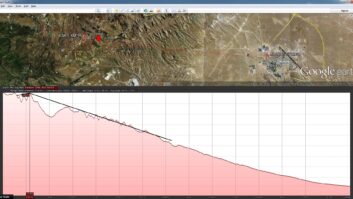
The filter built according to the above calculations and specifications was constructed for use at a transmitter site near Hamilton. There were two transmitters then, on 1296 kHz and 1143 kHz, and the desired frequency for the backup feed was 756 kHz, from a transmitter in Auckland.
The actual measured response is shown at right in both graph form and as a tabulation at selected frequencies.
CONCLUSION
Prior to the construction and installation of the Bandpass Filters in several locations, the received signal quality was generally poor to unusable, mostly impaired by front-end overload of the receivers. Once the filters were in service, the received quality was excellent, certainly good enough to re-broadcast for several hours if necessary. Back in the ’80s, full audio bandwidth receiver availability was not great. Currently available receivers, for example from Inovonics, should give excellent results. With the changes to independent STLs, the requirement for off-air back-up program sources has reduced and there is now much less dependence on this system of Bandpass Filters and receivers in New Zealand.
Comment on this or any story. Write to [email protected].