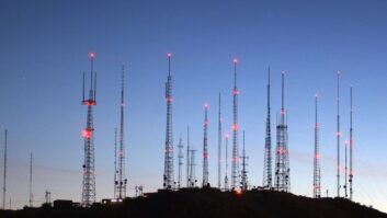
When Cumulus Media made the decision to sell the WMAL(AM) transmitter site that was located adjacent to the beltway north of downtown Washington, D.C. to a real estate developer, they contacted Stu Graham, P.E., with Graham-Brock Inc. to investigate possible host stations in the market where they could potentially diplex their popular news station. Mr. Graham identified WSPZ (now WWRC) with their transmitter site located in Germantown, Md., as a viable host station, and he designed a four-tower DA-1 pattern for WMAL utilizing the WSPZ array geometry to produce a southeast-directed pattern toward downtown Washington.
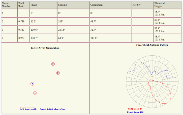
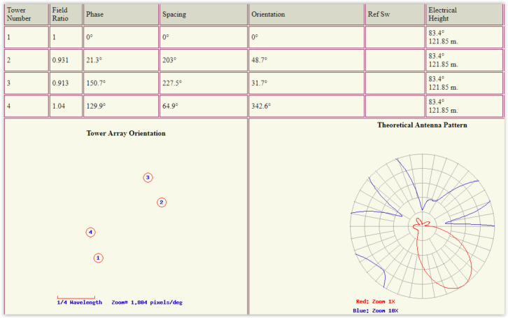
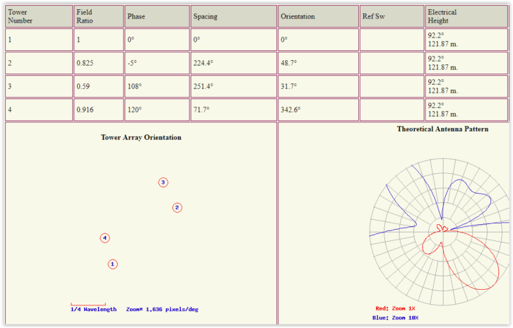
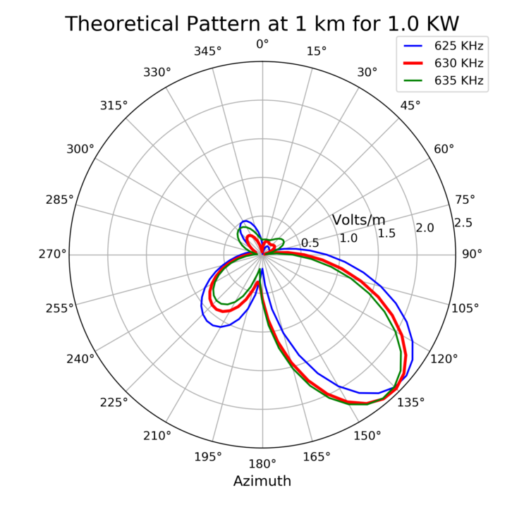
Figs. 1 and 2 illustrate the day and night WSPZ patterns, respectively, and Fig. 3 illustrates the WMAL pattern.
Once a lease agreement was consummated between the owners of WSPZ and Cumulus Media, Regional Engineer Dave Supplee contacted Kintronic Labs to inquire if it would be possible to diplex WSPZ on 570 kHz with WMAL on 630 kHz, with only 60 kHz separation at the low end of the AM band.
One consideration in this decision was that both stations utilized a talk format, which is not as demanding on the audio bandwidth of each station as would be the case if they were music format stations. Following a preliminary design effort, it was determined that the diplexing of these two stations would be feasible while realizing that the audio bandwidth of both stations would be reduced due to the impact of the filters required for isolation.
A site survey was conducted, after which the available space for additional networks at each tower base was determined. The decision was made to proceed with plans for a prefabricated transmitter building for WMAL due to insufficient space in the existing WSPZ transmitter building to accommodate two 10 kW transmitters plus the directional antenna phasing system. Following receipt of the construction permit, Kintronic Labs (KTL) was awarded a contract to supply the required diplexed antenna system as well as the prefabricated concrete tuning house required for WMAL.
SYSTEM DESIGN
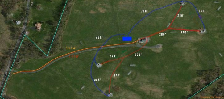
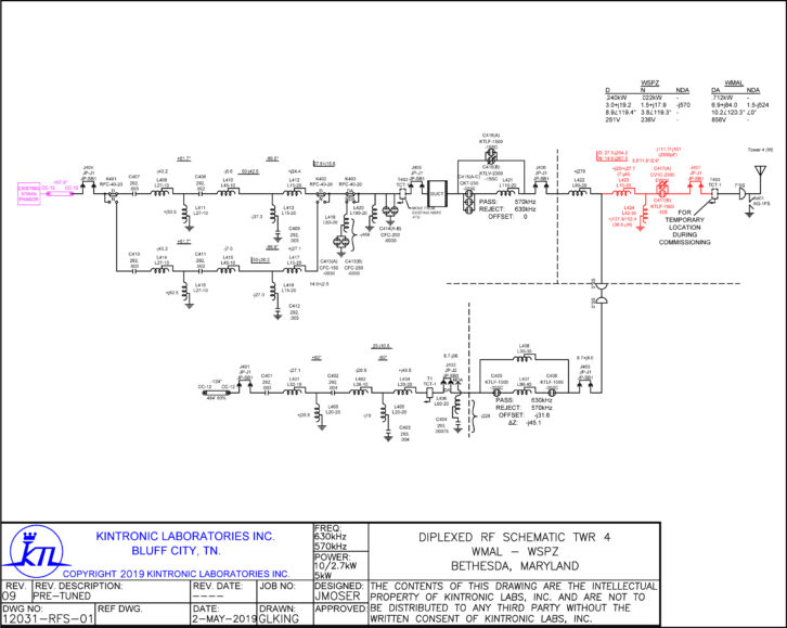
Rob Elder, Kintronic Labs contract field engineer, conducted open and short impedance measurements of the four towers at 570 kHz and 630 kHz. Final site layout plans were completed by Dave Supplee to establish the transmission line lengths for WMAL. Fig. 4 shows the routing of the transmission lines for WSPZ in red and for WMAL in blue.
Jim Moser, senior RF design engineer at KTL, proceeded with creating a model of the four-tower array using GNEC. A method of moments (MOM) simulation for the WSPZ day and night patterns and for the WMAL pattern utilizing the open and short tower measurements was conducted to yield the tower operating parameters for each pattern.
During the course of this project, WSPZ was sold, and the station call letters were changed to WWRC. We will therefore refer to WSPZ as WWRC for the remainder of this article.
In reviewing the design of the WWRC day and night antenna systems, we noted that the drive impedances of Towers 3 and 4 were in the single digits, and the associated power to these towers was very low compared to Towers 1 and 2.
These low-resistance towers typically have a negative impact on the common point buss impedance, resulting in a relatively narrow band common point input impedance. As a result a tower pre-matching “T” network was added to raise the resistance of these towers, which had the effect of enhancing the common point input on the patterns of both stations. These networks were added between the common output of the two series isolation trap filters and the tower feed for each tower.
Figs. 5 and 6 include the pre-match networks that were added to the Tower No. 3 and 4 tower feeds, respectively.
Series trap filters were designed for each station to facilitate the diplexing of the two stations. In addition, separate shunt filters were designed for installation at the output of the 570 kHz and 630 kHz transmitters in order to achieve a minimum of 60 dB of isolation between the two transmitters for the purpose of keeping any possible intermodulation products to an FCC-compliant level. A phase rotation “T” network was also added at the 570 kHz common point input to yield a left-facing impedance sweep contour on the Smith Chart at the final amplifier location.
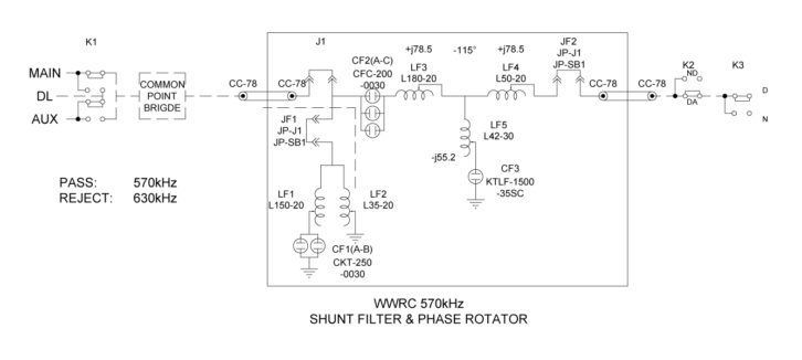
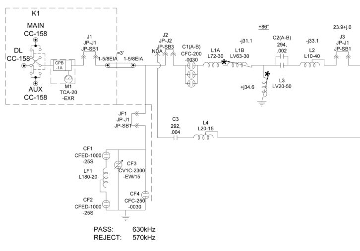
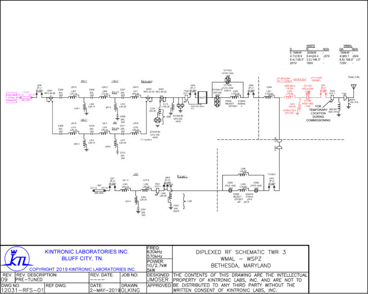
Fig. 7 includes the portion of the RF schematic of the 570 kHz pass/630 kHz reject shunt filter and phase rotation network installed at the WWRC common point input. Fig. 8 shows the 630 kHz pass/570 kHz reject shunt filter installed at the WMAL common point input.
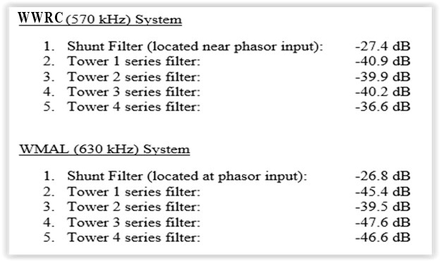
The measured rejection of each series and shunt trap filter in the diplexed directional antenna system is listed in Fig. 9. Note that the sum of the rejection of each series trap filter for WWRC or WMAL together with that of each respective WWRC or WMAL transmitter shunt filter yields a total port-to-port isolation of >60 dB. This was a major accomplishment for two frequencies only 60 kHz apart!
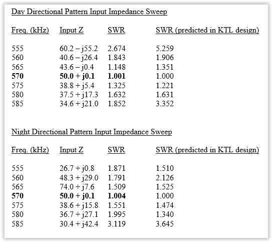
Fig. 10 compares the predicted versus measured common point VSWR values at Fc ±5, 10 and 15 kHz for the WWRC day and night patterns. It was a significant achievement to obtain VSWR values of <1.55:1 at Fc ±5 kHz for both WWRC patterns. An expanded Smith Chart display of the WWRC day and night common point sweeps is shown in Figs. 11 and 12, respectively. The red circle indicates a 1.5:1 VSWR.
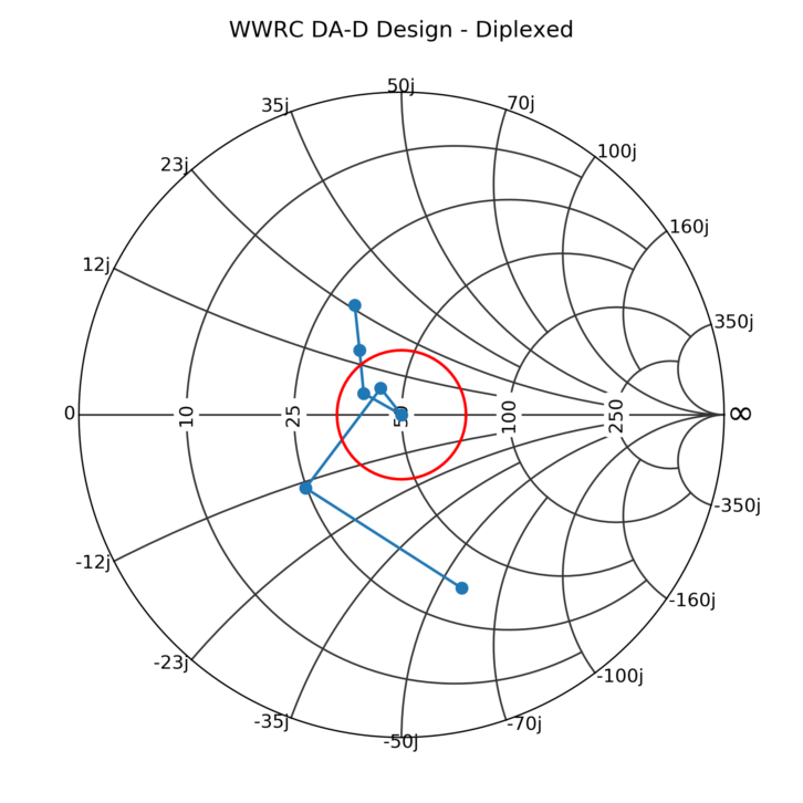
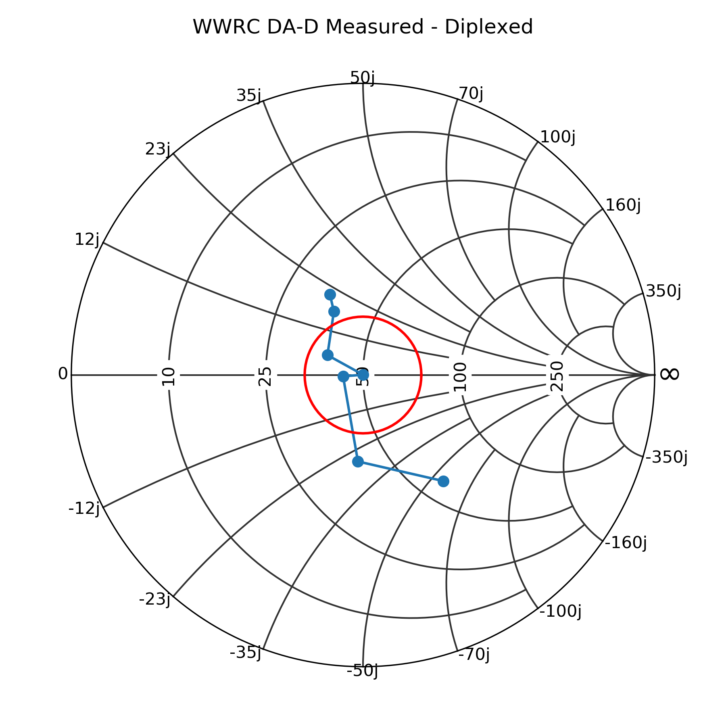
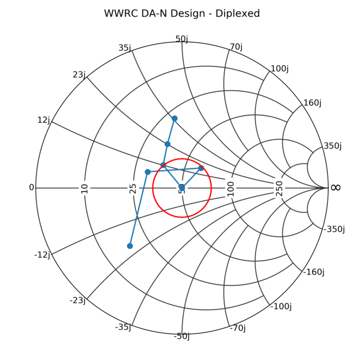
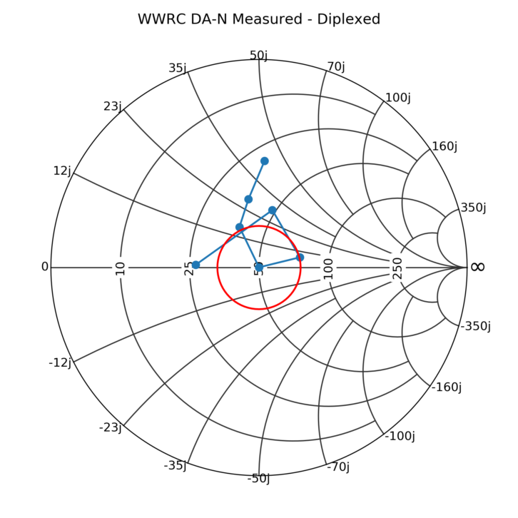
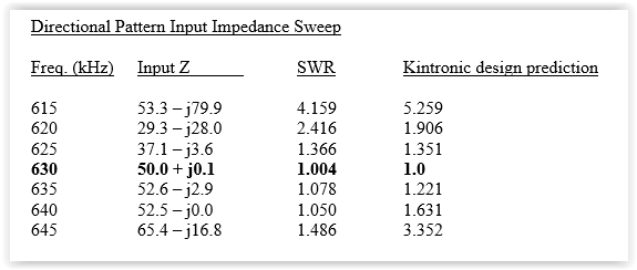
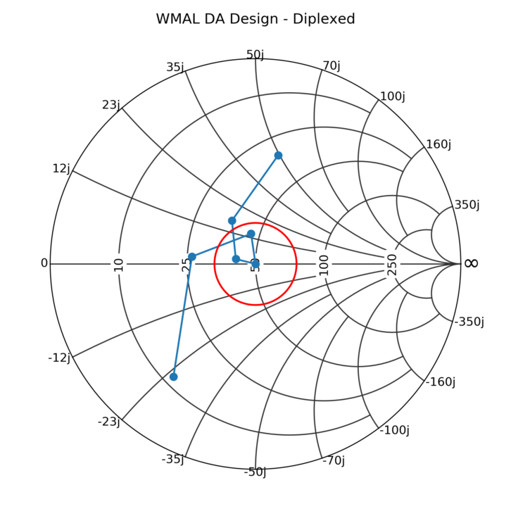
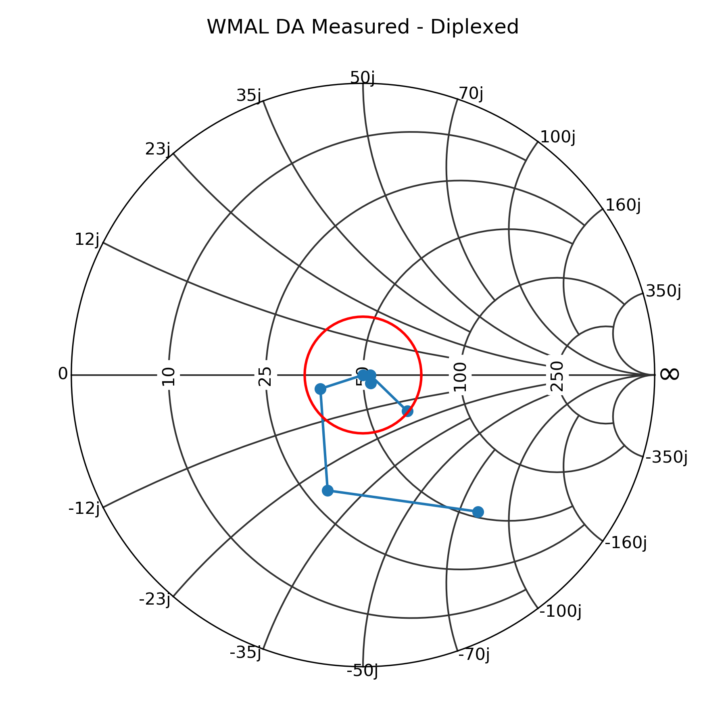
Fig. 13 compares the predicted versus measured common point VSWR values at Fc ±5, 10 and 15 kHz for the WMAL pattern. In this case, the sideband VSWR values at Fc ±5 kHz are < 1.37:1, which is a result of network optimization techniques utilizing the Kintronic Labs CKTNET and ARRAYPAT software design tools together with LTSPICE. Fig. 14 is an expanded Smith Chart display of the same input common point sweep data. The lower sideband that is closest to 570 kHz is asymmetric relative to the upper sideband due to the effects of the WWRC transmitter output shunt filter.
SETTING IT UP
All of the phasing and matching system adjustments were made utilizing the four-port network analyzer technique that was ingeniously developed by Ronald D. Rackley, P.E. (see Reference [1] at the end of this article). The instrumentation suite included a Hewlett Packard 8753 series network analyzer, a Tunwall Radio directional coupler set designed by Rackley, and an ENI linear amplifier.
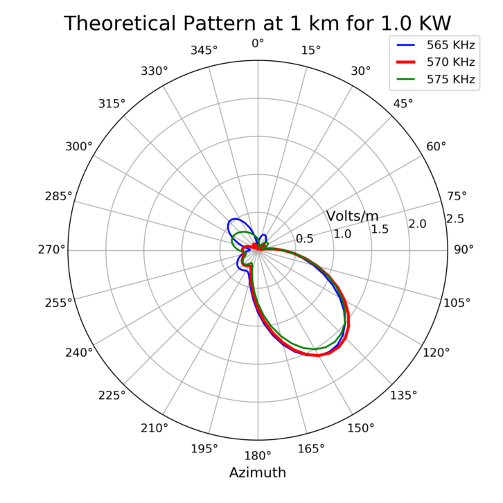
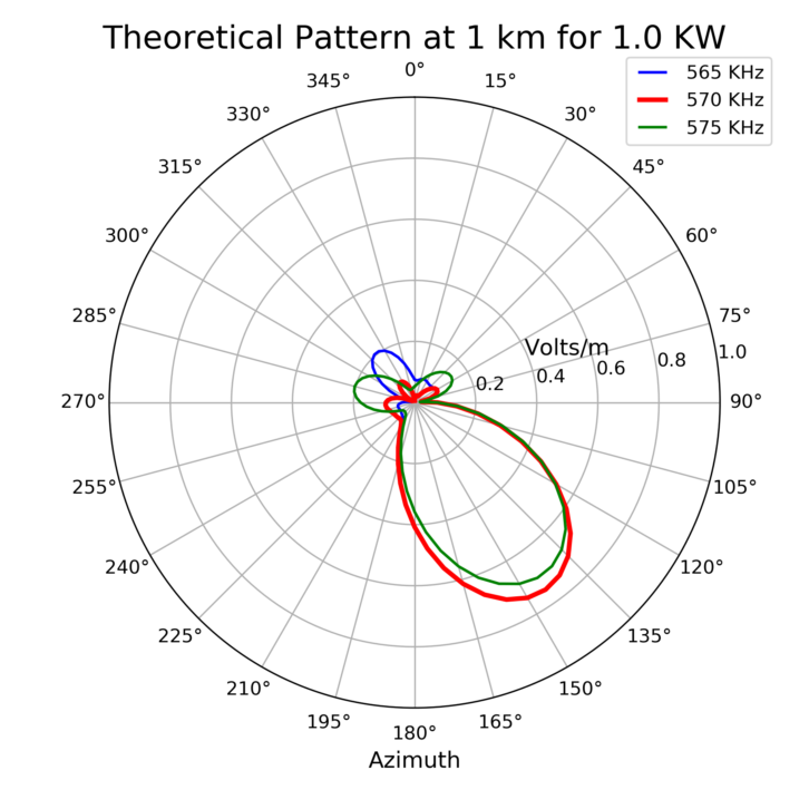
In addition to the Fc ±5 kHz common point impedance optimization for both stations’ patterns, we also predicted the carrier and sideband pattern bandwidth utilizing the Kintronic Labs ARRAYPAT software tool. The pattern bandwidth results for Fc ±5 kHz for the WWRC day and night patterns are shown in Fig. 15, where the carrier pattern is shown in red, the lower sideband in blue and the upper sideband in green. As you can see, the carrier and lower sideband patterns in the main lobe are overlaid whereas the upper sideband pattern, which is closest to the WMAL lower sideband, is reduced in field intensity relative to the carrier due to the rejection filter attenuation.
The solutions for phase budget were iterated to determine the reference tower phase which would result in the minimum field intensity variation versus frequency and minimum sideband VSWR for the WMAL pattern. The WMAL predicted pattern bandwidth is shown in Fig. 16. In this case, as you would expect, the lower sideband closest to the WWRC upper sideband is the most deviated sideband pattern from the carrier pattern.
IM MEASUREMENTS
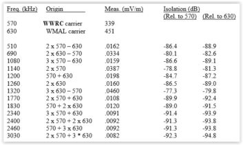
Following completion of the on-site adjustments for each pattern according to these optimized target values, a Potomac Model FIM-41 field intensity meter was utilized to measure all of the possible intermodulation products between the two stations. The results of the intermod measurements are shown in Fig. 17. The two frequencies that were slightly above the -80 dB threshold were WRVA on 1140 kHz and an unidentified station on 1320 kHz. The final impedance sweep data presented above was collected once these measurement results were verified.
WMAL PREFABRICATED CONCRETE TRANSMITTER BUILDING
Due to the lack of sufficient space for the WMAL transmitters and phasor in the WWRC transmitter building, Cumulus Media decided to install a pre-fabricated concrete transmitter building adjacent to the WWRC transmitter building in the location shown as a blue rectangle in Fig. 4. The building was sized to accommodate two Nautel NX10 AM transmitters, a Program Input Equipment (PIE) rack, a 15 kW dummy load and the WMAL common point and phasing/power divider networks in a shielded section of the building. Fig. 18 shows a foldout layout of the transmitter building.
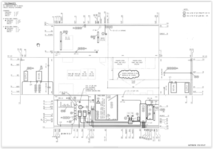
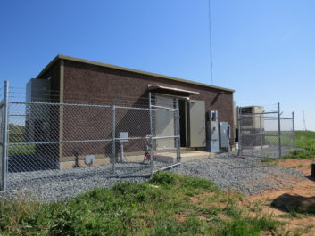
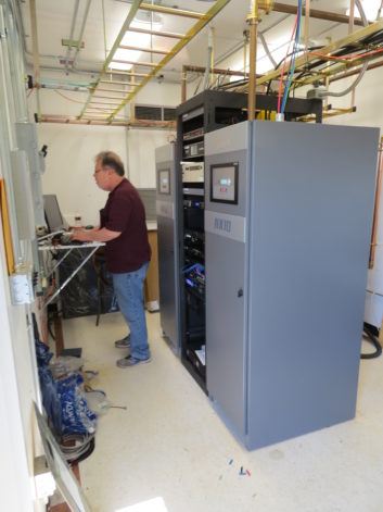
The two transmitters and PIE rack are centered in a row in the left end of the building and the open panel and shelf phasing and matching system encompassed in an expanded metal enclosure with interlocked access door is located in the right end of the building. A backup diesel generator and tank were installed outside the building closest to the electrical distribution panel and automatic transfer switch. A photo of the installed prefab building with the diesel generator located to the right of the building is shown in Fig. 19.
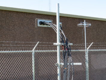
The transmission and sample lines were routed to the four towers via a bulkhead ground panel located in the upper rear wall of the building as shown in Fig. 20.
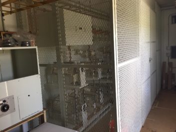
Figs. 21 and 22 show the phasing system installed inside an expanded metal shielded enclosure and the row of transmitters and racks, respectively.
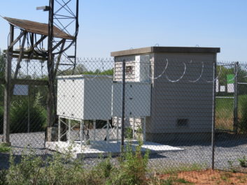
A photo typical of the installation of the WMAL matching and filter networks at the base of one of the WWRC towers is shown in Fig. 23. The large white weatherproof enclosures house the RF components for those networks. An array of STL isocouplers is shown to the left of the matching and filter enclosures.
THE VERDICT
The use of a combination of strategically designed common pre-matching networks at the towers, series and shunt trap filters with offsets, slope compensation elements and phase rotation networks resulted in the successful diplexed directional operation of WWRC and WMAL with only 60 kHz separation on the low end of the AM band. The final result accomplished a system with:
- a Fc +/- 5 kHz common point VSWR of < 1.37:1 for both the WWRC day and WMAL patterns;
- a Fc +/- 5 kHz common point VSWR of < 1.55:1 for the WWRC night pattern; and
- no measured out-of-limit intermodulation products.
This article is based on a presentation to the 2019 NAB Show Broadcast Engineering and IT Conference. A sampler of session papers is provided in the Conference Proceedings, which are available for purchase on USB Flash Drive at www.nabstore.com, keyword proceedings.
REFERENCE
[1] “Evaluation and Improvement of AM Antenna Characteristics For Optimal Digital Performance,” Ronald D. Rackley, PE, duTreil, Lundin & Rackley, Inc, Proceedings of the 2003 NAB Broadcast Engineering Conference.