In the Oct. 25 issue of Radio World, James O’Neal asks an interesting question. His article, titled “Doesn’t Anyone Build Anything Anymore?”, showed hand-built electronic equipment at broadcast stations in the 1960s and ’70s.
My answer to his question is “yes.” Some of us still do create solutions by hand, even in this plug’n’play world.
A BIT OF HISTORY
Back in the 1920s, ’30s and even the ’40s, most station engineers built their studio and transmitter equipment. There was some broadcast gear available from RCA, but it was very expensive until after WWII, when competition from other manufacturers increased.
I was licensed in amateur radio starting at age 16, in 1963. My greatest interest was designing and building electronic circuits. With a good understanding of Ohm’s Law and a desire to work with my hands, I have always enjoyed creating handy devices for use at radio stations. It is fun and rewarding.
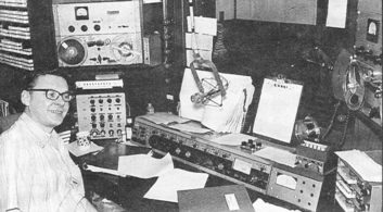
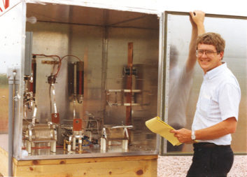
Fig. 1 illustrates that point — it features a main studio that I built at a small radio station in Brainerd, Minn. The announcer is Don Kelley. Sorry, it is a fuzzy vintage photo!
Looking closely, you see a number of interesting innovations. On the lower left is a painted wooden box with a metal panel containing numerous knobs and switches for dealing with multiple audio feeds to the 1964 vintage Gates Yard tube-type studio audio console.
If you know that audio mixer, you’ll wonder what the second meter is to the right. Well, it is the modulation monitor. Announcers could easily see their studio audio levels and the resulting transmitted audio. That extra meter was in a painted metal box with the same size and front panel tilt as the audio console. It was an extension for the console, not just a box that did not fit well into the studio environment. Atop that was a keyset for selecting phone lines to go on the air.
Further to the right was an ITC triple-deck cartridge playback machine. Remember those? Attached to its right side is a box with pots to control the audio level of each cartridge playback deck. It made sense to make the final audio product a good one, even in the hectic live studio environment of the time. Yes, those are Magnecord PT-6 reel-to-reel tape machines in wooden boxes on the wall with space below for other broadcast gear. The arrangement made maximum use of available space.
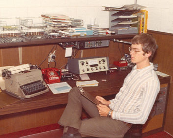
Fig. 2 shows the station newsroom. Yes, radio stations did real news reporting back then. (The handsome skinny guy with the clipboard is me!)
Of greatest interest here is the six-input audio console. No, you won’t find one in a manufacturer’s catalog. I built it from scratch and loved doing it. The console was designed and sized for that particular situation. There are boxes above, including one with an analog clock timer so news cuts could be timed. What’s missing is a computer … well, those came later.
MOVING ON
One radio station was not enough for the young and energetic person I was. So it was off to do more in the world of radio broadcast engineering.
That included Fig. 3, building AM directional antenna systems from the ground up with coils and capacitors instead of installing manufactured phasors. You can still do that — if someone wants one!
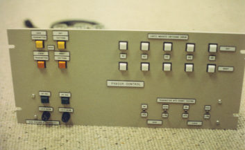
Fig. 4 shows a phasor controller for a five-tower AM array. Why buy when you can build one instead? This one has no less than 24 relays on the chassis behind. I designed and built it using real-world experience for what goes wrong during lightning strikes, etc. That controller and AM directional are still working after more than 30 years of service. (Manufacturers need to do more of that kind of thinking when designing equipment today.)
HOW TO DO IT
I came from a point-to-point wiring scheme world where resistors and capacitors were wired and soldered directly to tube sockets and the like, so my circuit boards do not have etched lands to connect through-hole components.
Instead, I have always preferred running wires on the noncomponent side of a board.
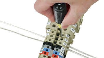
I like Vector-brand prototype boards, which have convenient holes every 1/10th inch. They are great for traditional dual inline package integrated circuits and many relays. Fig. 5 shows that. The reasoning here is they are quick and easy to wire, especially in situations where maybe only one board is built for a particular need.
TAKE PRIDE IN YOUR WORK
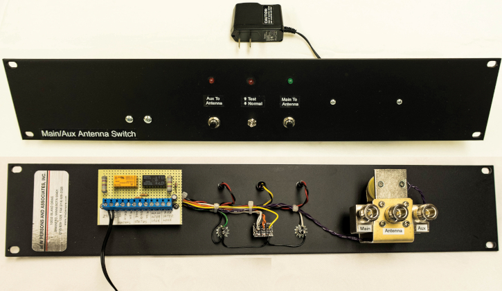
Fig. 6 shows a more recent shop creation to select one of two antennas. It is on a rack panel that is 3-1/2 inches high. Labels came off an inexpensive Brother P-Tech label machine in just seconds. Other label printers do that too. The lettering is white on a clear strip to let the panel’s black color show through. (Now this is starting to look like it came from a factory and something to take pride in.)
Don’t forget to create a schematic, even if it is hand-drawn. Every electronic device needs documentation so it can be serviced and/or modified in the future.
LIABILITY HAZARD
Fig. 6 also shows the backside of that same panel. Again, it is point-to-point wiring with a small circuit card for two relays and other components including an input/output connector. Note also that there is a wall-wart (wall mount) power supply.
I am afraid nowadays to connect a 120 VAC power cord to even one of my creations. The liability is very high. That problem goes away when I use UL approved external power supplies with outputs of less than 30 volts. Almost all are lightweight switching power supplies with small form factors. Another benefit is they save time and money because a DC power output is already tightly voltage regulated.
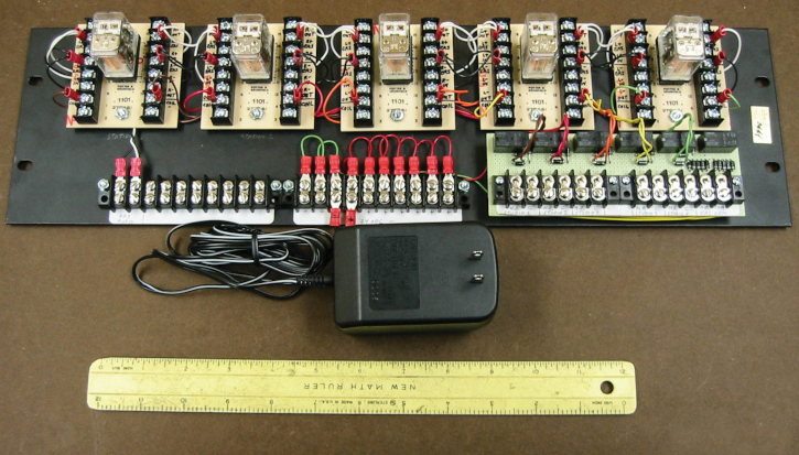
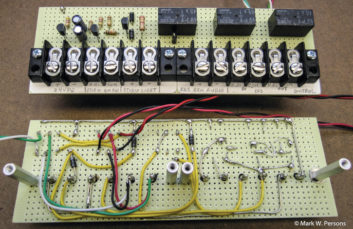
Fig. 8 is a relay panel used for controlling audio to multiple radio stations by one EAS unit. This project makes use of readily available Potter & Brumfield brand circuit cards with relays. There is even room to hand print labels on each relay card. Again, there is a wall power supply to decrease liability.
It is true that almost no one builds equipment anymore. It takes a well-equipped shop with a drill press to make equipment that does not look haphazard. The person doing it must have a good understanding of the electronic technology he or she is working with.
I feel great about making something that is useful and looks much like what a manufacturer might mass produce.
However, like many engineers of my vintage, I am about to retire. At age 70, I am going to close the shop at the end of 2017.
The problem with continuing in business is $5,000 in taxes, accounting and insurance per year, which is not a good plan for an old guy like me. It is up to younger engineers to carry on the torch of broadcasting into the future.
You can still build equipment though. It makes perfect sense.
Comment on this or any article. Write to [email protected].
Mark Persons, WØMH, is a Certified Professional Broadcast Engineer and has more than 40 years’ experience. His website is www.mwpersons.com.