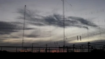
A station’s antenna and its siting can be critical to its commercial success. Incorrect choices are difficult to evaluate and expensive to fix.
Without the professional analysis of an experienced consulting engineer, some managers may have a tendency to choose and install FM antennas with a certain amount of misplaced belief, often based on “street lore” and emotion.
To provide some insight into this subject, three prominent broadcast consulting firms were asked to respond to 15 topics about FM antenna performance. The first of the consultants’ responses are shown below, and the rest will follow in future issues.
The participants are Ben Dawson of Hatfield & Dawson; Bob Culver of Lohnes & Culver; and Don Markley of D.L. Markley & Associates.
Note that any consultant would need specific site and application information to provide an accurate recommendation for a given situation.
1. Number of antenna bays vs. antenna height AGL vs. ERP vs. terrain profiles.
Ben Dawson: The proper selection of high-gain antenna configurations, such as those for UHF TV with typical gains of 30 or more, requires careful evaluation of the terrain so that the combination of gain, beam tilt and horizontal plane pattern provides more or less uniform illumination of the desired service area.
This is less troublesome at VHF frequencies, where the antenna gain typically is lower, but it still should be the basic determining factor in most situations.
Bob Culver: The antenna vertical pattern, being controlled by the antenna aperture length (hence number of bays and spacing) is the issue here. Obviously this is a tradeoff relative to antenna gain, transmitter power output (TPO), necessary line size (power rating) therefore loss, station ERP, antenna height, line length (loss), etc.
There are a multitude of interrelated variables that have to be considered to arrive at the desired end results. Some variables will be primary in that there is little room for change.
For example a very low antenna height may dictate 1/2-wavelength bay spacing and perhaps a short antenna aperture. On the other hand, a remote location may supply a limited prime power capacity and therefore a low transmitter power, requiring a relatively high antenna gain and low loss system.
Don Markley: For best service, we usually recommend the maximum power and height for the class of station with a reasonable number of bays of antenna. Like many FM criteria, this is a judgment call.
For example, you don’t normally go after 100 kW ERP with a two-bay antenna. On the other side, avoid 12 bays if you can. We usually recommend three or four bays for Class A, B1 or C3, five or six bays for Class B or C2 and eight bays for Class C0, C1 or C.
This also requires some judgment regarding the terrain in the area. In very hilly or mountainous terrain, use fewer bays and more transmitter power. High-gain antennas seem to work best for level terrain such as on the prairies out west.
2. Vertical bay spacing (effect on non-ionizing radiation on the ground near the site and other pattern parameters).
Dawson: Reduced spacing (typically 0.95 lambda or lower, down to 0.5 lambda) provides substantial benefits in reduction of nearby NIER levels, reduced potential for site electromagnetic incompatibility and reduced foreground reflection.
Culver: I have no problem with using reduced-bay spacing to achieve reduced ground-level RF energy exposure level. Using 1/2-wavelength spacing is physically easy with some antennas where a 180-degree phase shift can be arranged by inverting the antenna elements and will then work with a 180-degree inter-bay line length.
Reduced spacing, but not 1/2-wavelength will reduce downward and side lobe signals. This can be used where less spacing is not physically possible (panel antennas) or electrically desirable.
The resulting vertical pattern is determined by the full antenna assembly. Some individual elements are inherently suppressed in their downward signal and the array can be more easily built to limit downward signal.
Markley: We normally just use one-wavelength spacing unless there is a problem with close-in radiation.