The author is former managing partner of Hatfield & Dawson Consulting Engineers and is a senior consultant to the firm.
While cell site towers and monopole masts have long been potential nuisances and sometimes severe impairments to the operation of nearby AM antennas, they can actually be useful as AM radiators in some situations.
The relaxation of the AM antenna efficiency requirements in the AM Improvement rulemaking has provided flexibility by revising the rules which previously made use of electrically fairly short towers and restricted ground system areas difficult (see reference [1] found later in this paper). Cell site antenna support structures vary widely in height, but many are tall enough to be suitable for use as antennas at AM frequencies.
We at Hatfield & Dawson began to investigate the possibility of using a cell site monopole for an STA antenna for an AM station in about 2004, well before the time when the FCC promulgated its efficiency rule changes. We discussed the possibility with the tower owner, and obtained assurance that they would entertain the idea of use for a low power AM operation. The idea didn’t go further at that time because the then-licensee was not sure they would relocate and rebuild.
RON RACKLEY’S WSRQ CP APPLICATION AND LICENSE
Ron Rackley’s client, WSRQ, had been operating with a temporary antenna under STA, but evidently was unable to continue at the STA site, or to construct previously approved directional facilities. When Ron was given the problem in 2016, he knew of our previous cell tower analysis, was aware of a cell site/communications tower of substantial height in an acceptable location, and advised his client to investigate its possible use. When the result was favorable, hFM te prepared an application for construction permit to use the site.
Two technical matters regarding use of this antenna tower required resolution. The first was the feed system arrangement, and the second was the ground system and resulting antenna system efficiency analysis.
The cell/communications tower is 185 feet (56.3 meters) in height, which represents an electrical height of 82.5 degrees, and therefore is tall enough to be an acceptable AM radiator. However, like nearly all cell and communications masts, monopoles and towers, it’s grounded. While detuning of grounded antenna support structures is generally accomplished with a skirt of three or more vertical wires, this was not a practical feed system method because of the multiplicity of antennas mounted on the tower.
A detuning skirt generally exhibits low RF burn hazard and can easily be temporarily disabled by “grounding” to the support structure in the vicinity of any necessary work. A driven skirt, however, has higher RF burn potential, and would require an off-air period while work is performed on the tower.
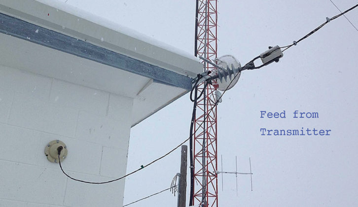
Skirts also add non-trivial amounts of wind loading, deadweight and leg stress, reducing the total capacity of a tower for additional load. The solution was to feed the tower with a slant wire feed. See Fig. 1.
(To see all of the images for this story, click on the slide show below.)
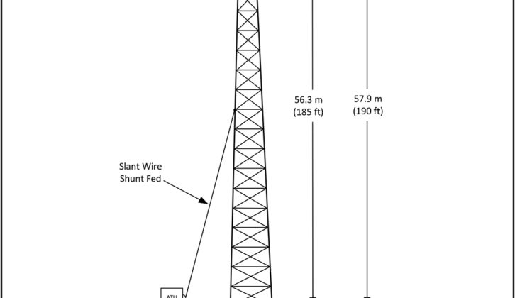
Precedent for use of a slant wire feed had been obtained by our office in the application for license of station KFIO in April 2017. Ron used that precedent and showed a NEC-4 analysis of the essential circularity of the proposed WSRQ radiation pattern at horizontal and vertical angles, within 1.5 dB up to elevation 70 degrees. This result is consistent with the KFIO situation, and most all other slant wire feeds for towers of about 135 degrees or shorter, as is shown in our previous work [2]. Since many cell and communications towers are relatively short, slant wire feeds for AM use can often be a very desirable feed solution.
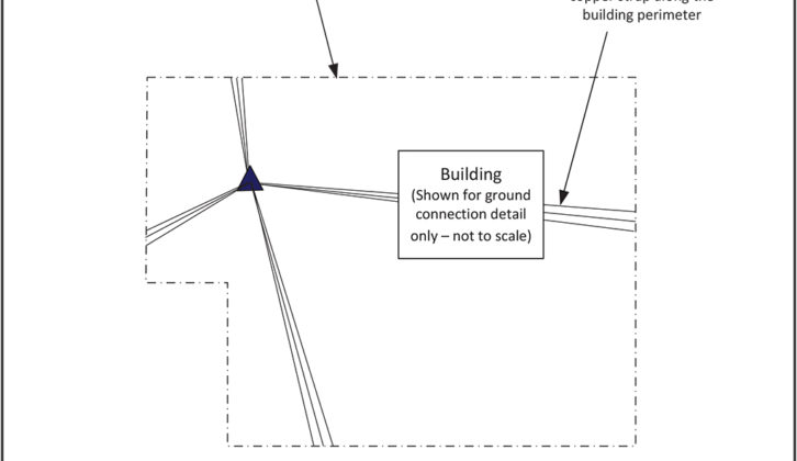
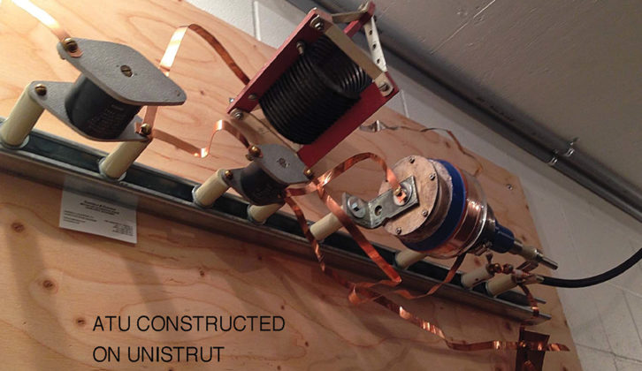
A NEC-4 analysis was also performed to determine the radiation efficiency of the proposed antenna, since the property parcel was very limited in size, as is typical of cell and communications installations. See Fig. 2.
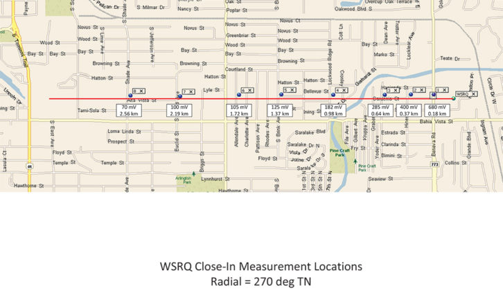
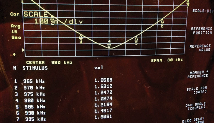
Geometry showed that the site allowed a radial ground system equivalent in size to a 21.7-meter radius circle, or about 32 electrical degrees. This is well below the variables allowed by the FCC’s “Figure 8” table and computer program, which are of dubious provenance in any event. Although the construction permit was granted without a requirement for any efficiency measurements, a single radial was measured, and confirmed the calculated value. See Fig. 3.
The WSRQ construction permit was granted in November 2018, and the station is now licensed.
THE PENDING APPLICATION FOR CONSTRUCTION PERMIT FOR KARR
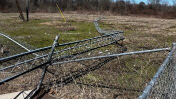
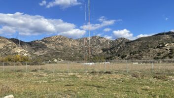
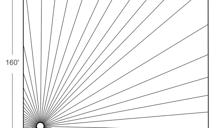
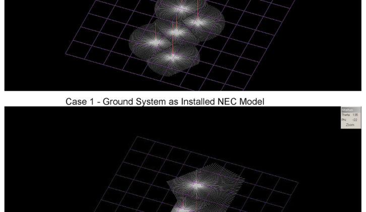
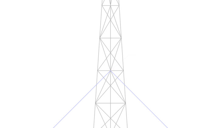
Our original analysis of possible cell site use for an AM station in 2004 was for KARR, a station that had lost its original transmitter site to development. The station licensee was unable to find any other possible permanent location except for, as in the WSRQ instance, a fairly tall cell tower on a small property parcel. See Fig. 4 for an idea of the constraints of the ground system.
The cell monopole itself is 150 feet in height (45.7 meters), 80.1 electrical degrees, and its antenna platform adds a bit of top-loading. The site size allows a 120 radial ground system of average length 0.134 wavelength. This radial system, like the WSRQ example, is well below the correction range of the FCC Figure 8 graph and computer algorithm.
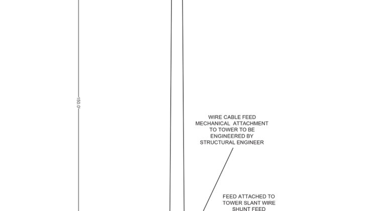
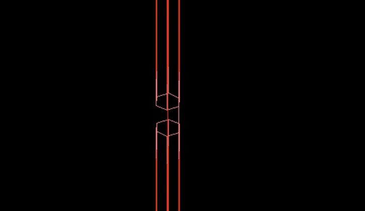
The detailed model of the proposed slant wire fed, grounded-base, monopole tower is shown in Fig. 5.
The ground radials are modeled as #10 AWG wires buried to a depth of 0.15 meters (approximately 6 inches) in soil having a conductivity of 4 mS/m, and a relative dielectric permittivity constant (epsilon) of 15. This is the same dielectric constant used by the FCC in developing the Ground Wave Field Strength Versus Distance Curves in Section 73.184 of the Commission’s Rules and Regulations.
The NEC-4 files are over 90 pages and impractical to put in this report, but can be accessed on the FCC CDBS website at: https://tinyurl.com/karr-report.
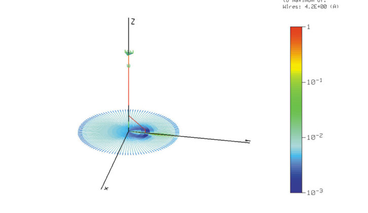
Fig. 6 shows the model-predicted current distribution on the monopole.
Based on the results of the NEC-4 modeling, the predicted vertically-polarized RMS attenuated electric field at one kilometer is 197.1 mV/m, assuming a soil conductivity of 4 mS/m and a dielectric constant of 15.
From this attenuated value the predicted unattenuated field (antenna efficiency) was determined from the Ground Wave Field Strength Versus Distance graph (1430–1510 kHz) of Section 73.184. From the graph, for a referenced radiated field of 100 mV/m at one kilometer, the attenuated field at one kilometer for a soil conductivity of 4 mS/m is 76.7 mV/m. Stated differently, the 4 mS/m soil is predicted to attenuate the field by a factor of 0.767 when compared to the 100 mV/m unattenuated field at one kilometer. Therefore, the model derived attenuated RMS of 197.0 mV/m at one kilometer can simply be divided by 0.767 to yield the predicted unattenuated RMS field of 256.8 mV/m/kW at one kilometer.
Using the same NEC-4 model, the attenuated field strength in the horizontal plane varies from 196.1 mV/m to 200.8 mV/m, providing a circularity of 0.2 dB.
The application for construction permit is pending as of the time of this writing [3].
THE “FM TOWER” SPECIAL TEMPORARY AUTHORITY
Another site loss case resulted in an STA for use of an unusual wire antenna supported by the grounded guyed tower of a commonly-owned FM station. The tower guys were uninsulated and grounded at their outer ends as well, as is the usual case for towers not designed for AM use.
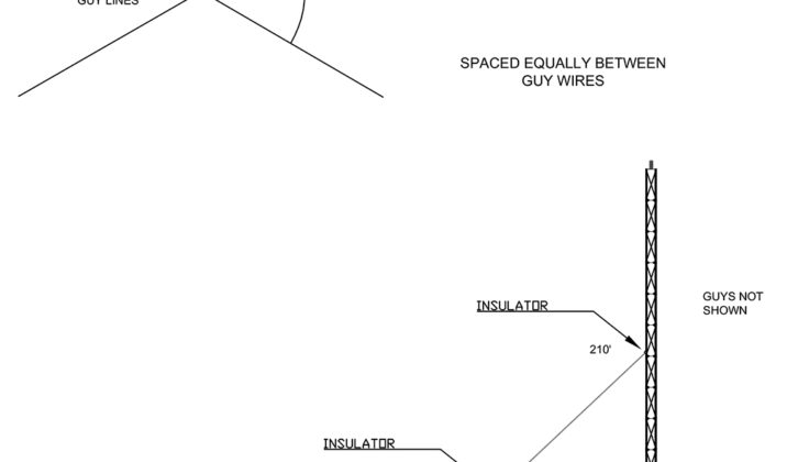
The grounded 300-foot guyed uniform cross-section antenna tower of was fed with an “umbrella spoke” wire, mounted and configured as shown in Fig. 7.
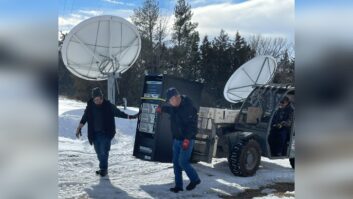
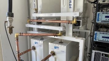
The base of this wire was terminated on the existing equipment building, and the matching network and transmitter were installed inside the building. Figs. 8, 9 and 10 show the details of the installation.
This installation also had a very cursory limited ground system. Six radial “ground” wires, extending to a distance of about 200 feet from the antenna tower (about 70 degrees) were installed. The radials were barbed wire laid in the snow (it was December). Barbed wire makes excellent radials for use in some specialized situations, and is far cheaper and less susceptible to theft than copper or even copperweld.
The efficiency for this antenna installation, based on reasonable ground conductivity assumptions and a moment method model, is about 200 mV/m/kW/km. The radiation pattern is modestly directional. Connection of the “umbrella spoke” at its upper end to the tower would result in a less directional pattern, but also a higher drive impedance.
USE OF MOMENT METHOD ANALYSIS FOR SHORT OR ODDLY-SHAPED GROUND SYSTEMS
Dave Pinion, Steve Lockwood and Joe Overacker in our office have just completed an extensive NEC-4 study showing that considerable modification of the ground system in a complex diplexed DA has essentially NO effect on the system efficiency. This situation will be an increase in total ground system area, but with an irregular configuration.
Similar studies have been performed on situations with extensive reduction of outer ground system area, and the results confirm that the “normal” 120-radial 90-degree ground system is overly conservative [4].
Fig. 11 shows the situation in the “before” and “after” ground system configurations.
The conclusion is that the lack of scaling for frequency in the Brown and Epstein experiment analysis, the source of the original 120 ninety degree radial requirement, has cost hundreds of miles of copper wire to be unnecessarily wasted.
SYSTEMS WITH NO GROUND RADIALS
A system using a relatively tall tower that does not have a base insulator but is grounded only with a few driven rods and has no radial ground system has been employed in two or three implementations which were licensed by FCC, originally at WNTF.
This arrangement uses slanted wires from close to mid-height on the tower, slanting in an umbrella arrangement to locations a short distance from the tower base. The wires are fed against the grounded tower [5]. See Fig. 12.
The complete lack of a radial ground system isn’t damaging to the efficiency, since the lower portion of the skirts or the “umbrella” together with the tower itself create a quasi-dipole, and, there is a path for the displacement current return, thus satisfying Kirchoff’s law. This result is similar to the use of elevated radial systems, with as few as four or six radials.
A quasi-dipole can also be created by a pair of skirt-wire assemblies on a grounded tower of sufficient length. A NEC-4 model using a pair of 50-degree skirts shows this configuration in Fig. 13.
This example falls slightly short of the FCC’s minimum efficiency requirement, but would be valuable for an STA. It could be easily modified to meet the FCC minimum value if a slightly taller grounded tower were available.
CONCLUSION
The conventional wisdom about the necessity of “ground radials” of substantial number and length is simply far too conservative. Innumerable examples of antennas with restricted or convoluted ground systems have been in operation for many years, based on simplistic analysis or field measurement confirmation. But modern analysis methods clearly show that the efficiency of unusual restricted area and unusual geometry ground systems — or in some cases no radial ground system at all — can meet the current minimum efficiency requirements of the FCC.
Benjamin F. Dawson III, P.E. has over 60 years of experience with broadcast antenna systems and other applied radio physics matters.
REFERENCES:
[1] 1st R&O, FNPRM, NOI; MM Docket 13-249, at paragraphs 41–48 (October 23, 2015)
[2] Dawson, B., “The Slant Wire Fed Monopole, a Neglected but Invaluable Technique,” paper presented at the 60th Annual Institute of Electrical and Electronic Engineers Broadcast Symposium, October 2010.
[3] Other examples of the use of moment method analysis to determine effective field of unusual antennas or antennas in unusual situations include: WRGC BP-20190130ABH, KSSK BP-20180921AAW, KIKI BP-20180921AAS and KHVH BP-20180921AAV.
[4] Dawson, B and S. Lockwood, “Revisiting Medium-Wave Ground System Requirements,” IEEE Antennas and Propagation Magazine, August 2008. Trainotti, V and L. Dorado, “Accurate Evaluation of Magnetic- and Electric-Field Losses in Ground Systems.” IEEE Antennas and Propagation Magazine, January 2008.
[5] Christman, A and C. Beverage, “The AM Umbrella Antenna,” IEEE Transactions on Broadcasting, June 1999.