Ken Beckwith is a field engineer with EMF based in Nebraska. Being a hands-on engineer, Ken has done his share of construction over the years. One of his projects was the construction of an octagonal-shaped AM loop EAS antenna using PVC pipe.
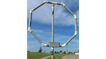
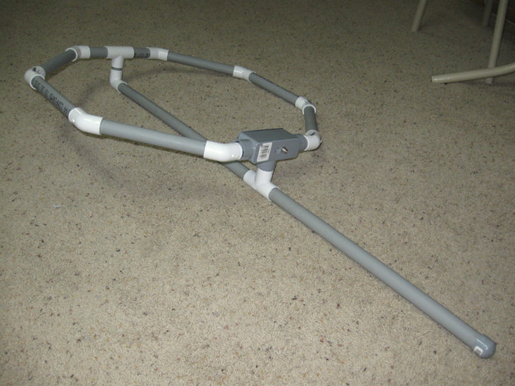
Before you begin this project, check out the completed antenna, shown in Fig. 1. The visual will help you piece all the angled elbows and tees together.
Note that to improve the strength of the loop, Ken added a piece of conduit down its middle.
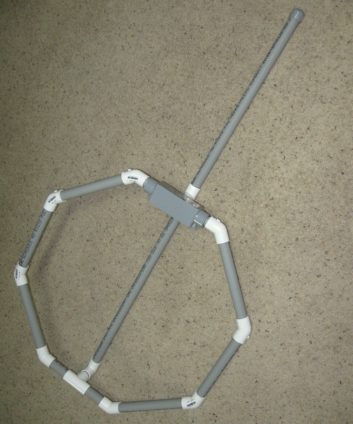
Construction starts with one tee, to which you attach two 4-inch pieces to the arms of the tee. The 2-1/4-inch piece attaches to the bottom of the tee. The 90-degree elbow attaches to the other end of the 2-1/4-inch piece, but save that step until later.
Two 45-degree elbows attach to the 4-inch pieces so they lay flat. This is so the “tail” of the tee is at 90 degrees, as shown in Fig. 2. The 9-1/2-inch pieces of PVC attach to the elbows next. Then, another set of elbows and another set of 9-1/2-inch pieces.
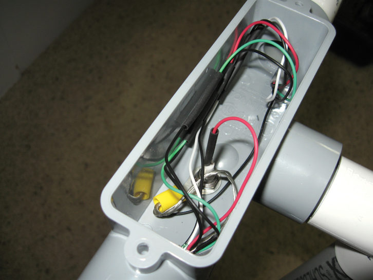
Continue with a third set of elbows, and the 9-1/2-inch pieces. Attach the 2-1/8-inch pieces to the last elbows. The “tee box” is connected to the 2-1/8-inch pieces, so the bottom of the tee sticks up parallel with the tee at the top of the antenna.
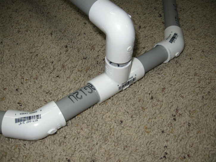
Attach the 23-1/4-inch piece to the 90-degree elbow, mentioned above, and then attach the other end of the elbow to the 2-1/4-inch piece on the top tee. Position it so the bottom end will connect to the remaining tee at the tee box.
Attach the 2-inch piece to the tail of the remaining tee, then connect it to the 23-1/4-inch piece so the 2-inch piece fits down into the bottom of the tee on the tee box, as shown in Fig. 3.
Attach the remaining piece of conduit to the other end of the tee, and attach the end cap to the end of that piece, to complete construction. Assemble the parts without glue, first. Once everything is fitted properly, use PVC cement to make a permanent bond.
After the glue is dry, fish a pull string through the conduit loop. A vacuum cleaner will make the job easier. Tie the Belden cable to the end of the pull string, and secure with electrical tape. Pull the cable through the pipe.
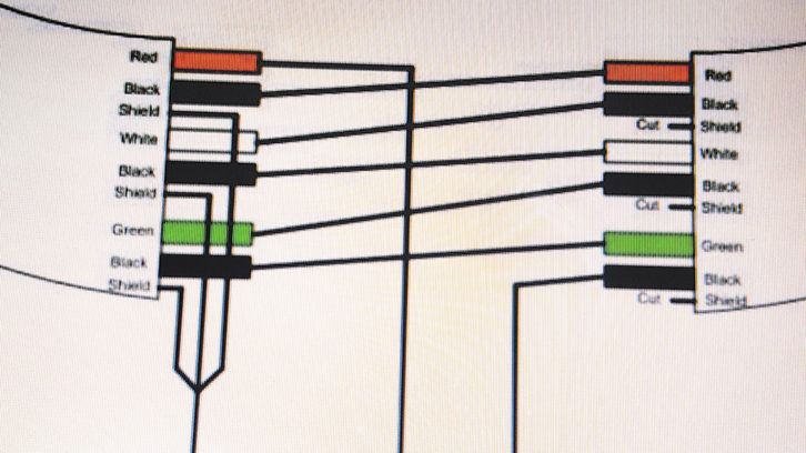
Strip the jacket off both ends of the cable and unwrap the shielding foil from each of the three pairs, and from both ends. Cut the shield wires off only one end of the cable. Join the ground wires at the other end together. Take the red wire next to the shields and lay it with the shields. It will be connected later. Take the other end of the red wire and connect it to the opposite end of the black wire paired with it. You’ll want to solder these connections, and cover them with a short piece of heat shrink or electrical tape. You will be making a six-turn coil using the multi-pair wires.
Now take the other end of that black wire, described above, and connect it to the white wire on the opposite side. The second end of the white wire connects to the black wire of the same pair at the first end. That black wire then connects to the green wire on the opposite side. The second end of the green wire then connects to the opposite end of the black wire it is paired with. The second end of the black wire connects to ground along with all of the shields.
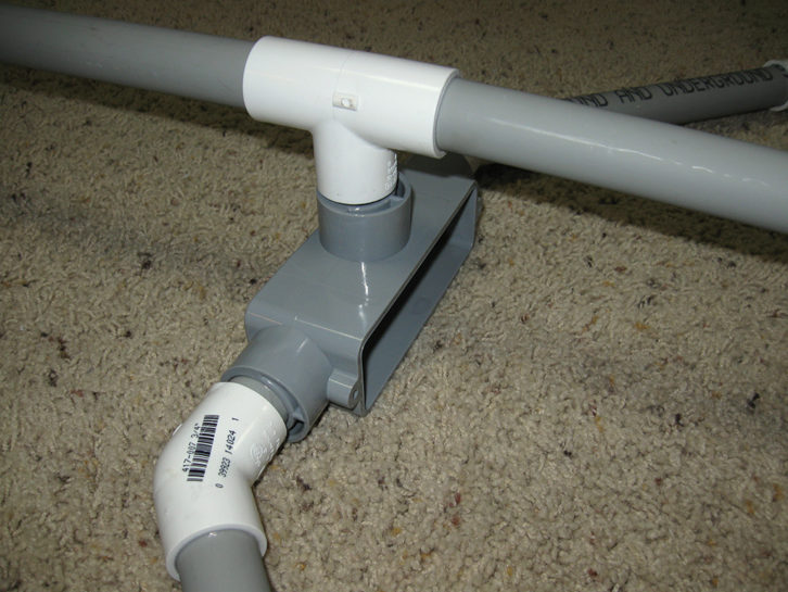
Confusing? Fig. 4 gives you a visual of the connections.
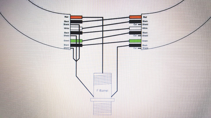
Once the connections are made, connect the shields and the black wire from the opposite side to ground using a 3/8-inch ring connector. That is held in place using the nut securing the F connector barrel to the tee-box housing.
The antenna has a broad coverage angle with a deep null when the antenna is broadside to the signal. Aim the “edge” of the loop toward the AM station you want to receive. The strongest signal will be received when the antenna end or edge is pointing to the signal source. The antenna can be mounted on a mast with U-bolts, hose clamps or whatever else works.
Here’s the construction parts list:
A 10-foot length of 3/4-inch diameter, schedule 40 PVC conduit cut into the following lengths:
2 – 4-inch
1 – 2-inch
1 – 2-1/4-inch
2 – 2-1/8-inch
6 – 9-1/2-inch
1 – 23-1/4-inch
Whatever is left over can be discarded, but before making your cuts, cut the flared end off, so all cuts are even.
1 – 3/4-inch 90 degree elbow
2 – 3/4-inch tee
8 – 3/4-inch 45 degree elbows
1 – 3/4-inch cap
1 – 3/4-inch tee box, plastic, with weatherproof gasket
1 – 7-foot piece of Belden 8777 or other three-pair shielded cable
3 – 7-foot single-pair shielded cables can substitute for Belden 8777
PVC primer and cement
Wire nuts or other connectors
1 – 3/8-inch ring terminal
F connector barrel with nut
Share your tips with other engineers in the pages of Workbench while qualifying for SBE recertification credit. Send your tips and high-resolution photos to [email protected].
Author John Bisset has spent 50 years in the broadcasting industry and is still learning. He handles western U.S. radio sales for the Telos Alliance. He holds CPBE certification status with the SBE and is a past recipient of the SBE’s Educator of the Year Award.