How can you get the most out of your FM antenna system? To provide some insight into this subject, three prominent broadcast consulting firms were asked to respond to 15 topics about FM antenna performance. The first responses were printed in the Nov. 21 and Dec. 5 issues. The next are shown below, and the rest will follow in future issues.
The participants are Ben Dawson of Hatfield & Dawson; Bob Culver of Lohnes & Culver; and Don Markley of D.L. Markley & Associates. Note that any consultant would need specific site and application information to provide an accurate recommendation for a given situation.
Topic: Value of pattern studies at antenna OEM test range:
Culver: Pattern measurements (“studies” is too vague a term, it could mean anything) can only be done on a test range as part of the manufacturing process.
It could be done after the antenna is built, in full size, but that is difficult. It is easier, less costly and used as a pattern development tool to make scale model measurements at about 450 percent of intended frequency.
Pattern measurements cannot be accurately made at any acceptable cost by any present method once the antenna is installed on the tower.
That is not to say that it will always be impossible, but no one has yet to disclose that they are using a method that isolates the antenna and its support from nearby structures and the terrain. It can be done, we know how to do it, but the tools and procedure have not been integrated yet!
If you want to know what pattern your antenna will develop, you must make the pattern measurements on a good antenna range. Most manufacturers have them.
Markley: We recommend that the proposed antenna and tower combination be checked on a range, either full scale or modeled. This is the only way to be able to accurately predict a station’s service area.
Topic: Desirability of using parasitics with a non-D FM antenna:
Dawson: An FM antenna with parasitics is not a non-D antenna.
Culver: Now we get to the real issue. An omnidirectional (non-directional) antenna is one that is inherently designed to be so. Its native pattern is a circle, or nearly so, to the point that it is considered a uniform circle for convenience.
This includes vertical arrays of inherently omni elements, ignoring their mounting, and panel arrays of proper size, mounting and with a feed of proper phase and magnitude to develop a circular or near circular pattern.
How lumpy can the circle be? Good question! The FCC has never adopted a definition of max/min pattern variations for omni antennas.
If you add a parasitic element to the antenna, it is not an omni. That is just my working definition and I know others disagree. You can do all the pattern work you want, try all the mounting configurations such as vertical position, spacing, angle, tower dimensions, etc. to see what the effects are and pick the one that creates the most circular pattern. That is “optimizing the omni pattern” to have the least harm (nulls in unwanted areas)
There is a middle ground that does the same thing, pattern tests as above, but never getting a pattern without some significant nulls. In that case the resulting nulls are oriented to have the least impact. That is the engineering of FM antenna omni pattern optimization.
Optimization as understood by the general manager, however, is different. It appears that the goal there is to get 250 percent of allowed ERP toward all of the populous areas, especially that fringe city nearby.
This is where the problem arises. If you file at the FCC for an omni antenna, you just specify the vertical pattern gain, which is easily estimated based on the number and type of elements and the vertical spacing. It is approximately 0.5+ per element for circular polarization (editor’s note: for one wavelength vertical spacing of the elements).
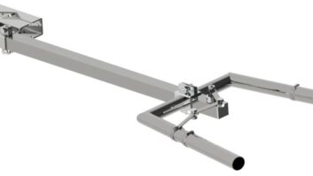
If you add any parasitic elements you have purposefully distorted the omni pattern and created a DA. True, you can purposefully distort the pattern with a selected mounting of the antenna, but adding parasitics makes that work obvious to the eye.
Now, if there are no parasitics used and the CP and license say omni, regardless of the resulting pattern the original antenna was omni and it can still be considered so. The FCC FM separation rules are based on an effort to avoid interference but they depend only on distance separation. If the resulting distortion creates a lot more or less ERP in some directions, the station can cause or receive more than anticipated interference.
Adding parasitic elements makes this potential very obvious, you can see the parasitic elements attached to the antenna! True, the intent may have been to “circularize” the pattern, but if the station is licensed as omni, there is no requirement to prove it is omni, there is no limitation on the “lumpiness” of the omni pattern and this presumption of circularity and minimum separation distances, but with actual excessive (or low) ERP can create cause (or incur) interference.
Markley: There is no reason to use parasitic elements on a non-directional antenna other than to correct for significant distortion caused by the mounting structure.
This can only be done on a range and must be carefully documented with before and after patterns to clearly demonstrate that the omnidirectional characteristics have been improved.
Otherwise, the FCC will consider the antenna to be directional and all calculations regarding ERP change from using the RMS gain of the antenna to the peak gain.


