This is the last in a three-part series, archived under Tech Tips at radioworld.com.
The heart of any effective lightning protection scheme is a central ground system.
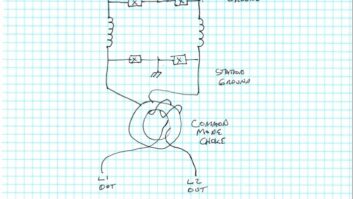
Such a system is shown in the diagram. Some call this a “star” grounding scheme because of the way all the ground conductors return to a central point or reference ground.
(click thumbnail)Proper grounding within a broadcast transmitter installation.If the transmitter building is located very near the tower, this ground can be the same as that for the tower itself. In many cases, however, there will be some distance between the tower and transmitter building, and in those instances, another array of ground rods should be provided.
All conductors operating at ground potential that enter or leave the transmitter building, including transmission lines, control cable shields and conduits, should be bonded to this ground array.
A single conductor from the ground rod array should be brought into the transmitter building via the shortest and straightest route possible. The point where it enters the building becomes the center of the “star,” or the point to which everything in the building is grounded. This is called the “station reference ground.”
All grounds in the building, including the safety ground of the electrical system (service entrance ground) and the ground conductors from all the equipment and outlets, then connect to this point. The diagram shows a properly designed station grounding scheme.
Protect and defend
Beware of having a separate ground rod connected to the electrical service entrance. Such separate rods are standard practice, but having a separate rod connected can spell trouble as a huge potential can develop between the station reference ground and a separate rod outside the system.
We (unknowingly) made this mistake at one of our FM sites in Michigan a number of years ago. Lightning hit the tower and the lightning current flowed down the rigid transmission line to the main transmitter, then through the transmitter chassis seeking the power company ground.
The Continental transmitter had two rows of fuses on the front panel of the power supply cabinet, and every one of those fuse holders was vaporized, leaving only the charred wire ends.
The investigation revealed a defective tower base electrode connection and no connection between the electrical service entrance ground and the station reference ground. Those items were corrected and we have since sustained numerous hits without further significant damage.
If you have a ground strap or terminus of an AM radial ground system coming into the transmitter building from the tower(s), be sure to connect it to the station reference ground.
(click thumbnail)A direct lightning strike produced pitting on the outside of this FM antenna bay and arcing within.
If there is no such strap coming from the tower(s), you do not specifically need one, but an advantageous location for a transmitter building is often at the end of the ground system at the end of the transverse ground strap. If this is the case, that strap may have been extended to connect inside the building.
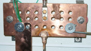
When connecting transmitters, racks and other equipment to the reference ground, it is important to do so in such a way that lightning currents will not flow through the equipment cabinets en route to ground.
On a transmitter, for example, make the ground connection as close to the RF output connection as possible. In that way, residual lightning currents coming in on the transmission line outer conductor can flow through the short copper path to the ground conductor and not through the metal of the cabinet.
Remember that such currents create a strong magnetic field that will induce currents into nearby unshielded conductors. By keeping surge currents out of the cabinet steel, this keeps them out of the transmitter’s wiring harness as well.
If the site has three-phase power, when it comes to lightning protection, a “wye” secondary on the utility power feed is preferable. This type of connection has several advantages, the most important of which are that every leg is referenced to ground (balanced with respect to ground) and the lower voltage (208) is easier to clamp in surge conditions.
Unless you specify a 208 volt wye, the utility company will probably provide a delta. Worse, they will probably save themselves a transformer and provide an open delta, which is terrible from a lightning protection standpoint. Note, 480 volt users will already have a wye configuration, so the above won’t be a factor.
Most all broadcast transmitters (with the exception of 50 kW AM rigs) will operate just fine on anything over 200 volts, so switching to 208 volts will pose no problems. A change of taps should be all that is required.
Beware, however, of the increase in current. Service conductors and disconnects sized for 240 volt operation may be too small for use at 208 volts. If undersized conductors are not replaced with those of appropriate size, a fire hazard will exist.
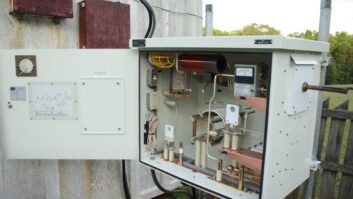
Suppression
A good surge suppressor is the only way to minimize lightning transients on the incoming utility power. These devices range from inexpensive “kamikaze” devices that work one time and have to be replaced, to very expensive series/shunt devices.
Somewhere in between is an economical device that will adequately protect the equipment at most every broadcast facility without breaking the bank.
The metal-oxide varistor (MOV) is at the heart of most shunt-type surge suppressors. These devices conduct when the potential across them exceed a threshold voltage. The devices must be rated to carry most of the anticipated lightning current.
This may seem like an impossible specification, but the device only has to carry the current for a very short period of time.
Modern surge suppressors are available with fused MOVs in many voltage ratings that will hold up well under typical lightning surge conditions, clamping the AC line to ground during the surge and thus protecting equipment downstream.
The fuses are designed to act slowly, holding their state for the short duration of the surge but blowing if the MOV becomes shorted as a result of excess current. The affected MOVs and fuses can then be replaced and the effectiveness of the surge suppressor restored.
Be sure to install the surge suppressor downstream of the main fused disconnect at the site. The ground connection from the surge suppressor must connect to the station reference ground. All the conductors to the surge suppressor must be relatively large, as the instantaneous currents that they will be called upon to carry can be substantial.
When it comes to surge suppression, the best policy is to buy all you can afford. If the budget can sustain a $10,000 series-shunt type, this will provide a high degree of protection. If the little “kamikaze” cans are all that the budget will stand, buy and install them.
Any working surge suppression is better than none. In practical terms, the insurance deductibles and premium increases you will save may well pay for one of the more expensive units in just a few years.
Filter
The final step in creating an effective lightning protection scheme is to build a low-pass filter into all your power, control and monitor cables.
This is easily done by placing a toroidal core over the conductors. This effectively forms an RF choke that presents a very high impedance to fast rise-time lightning and lightning-induced energy. Such cores are available from most mail-order electronic parts houses, and they come in a variety of sizes.
One such core should be placed over each of the cables entering a transmitter cabinet or rack. Run all the AC power wires through a single toroid. Pass the remote control cable through a core, and do the same with any small coaxial feeds (RF drive, mod monitor sample, etc.). Finally, for transmission lines up to and including 3-inch, install one or more cores on the cable just above the connector.
Larger, rigid transmission lines should be installed so that they form a “trombone” section, making at least three 90-degree turns before connecting to the transmitter. The 90-degree bends also present a high impedance to lightning and lightning-induced energy.
Elsewhere
The same principles we’ve discussed can also be applied at studio locations.
If there is an STL tower, make sure it is properly connected to a ground electrode array. Connect all transmission lines to that array where they leave the tower.
Use a “star” grounding scheme in the studio building with all leads returned to the center of that “star.” Make certain that the ground return point from anywhere to anywhere does not go through another piece of equipment. Use toroids on all low-voltage wires, and employ as much surge suppression as the situation can afford.
I used to tell people that the only certain way to protect a piece of equipment from lightning is to completely disconnect it from the outside world, including power, antenna, audio, data and control cables, and then put it under the bed where you are sleeping.
The device may still get hit, but then so would you, so it wouldn’t matter anymore.
That remains true. It really is impossible to protect anything from lightning completely, but by giving lightning a place to go that is away from our equipment and by making our equipment unattractive to lightning currents, we can eliminate most of the damage.