The author is account manager, radio transmitters for Rohde & Schwarz, handling Canada and the United States.
Liquid cooling for transmitters seems a bit exotic to many radio engineers, but truthfully, it’s anything but. Liquid cooling has been used for years including the large AM “flamethrowers” back in the 1950s and 1960s, as it was the only efficient way to push the heat out of the high-power AM tube transmitters. Some of these transmitters used an open-loop cooling design with fountains and cooling ponds for water that had been heated by the transmitter.
Engineers who have exposure to TV transmitters will know that liquid cooling is quite prevalent there, both with solid-state and IOT-based transmitters. Liquid cooling is becoming more prevalent in FM transmitters of late.
TRUTH IS STRANGER THAN FICTION
Every once in a while, you’ll hear an anecdote or even a horror story about water spewing all over the inside of a transmitter, causing massive failures and even fires. Most of these stories might as well have been written by Stephen King, because they’re both scary and largely fiction.
The truth is that today’s liquid-cooled transmitters are actually safer, simpler and easier to maintain than air-cooled transmitters … and far more efficient overall. A typical liquid-cooled transmitter features several things not found in an air-cooled transmitter.
First, inside the transmitter itself, each amplifier and power supply module is liquid-cooled, with channels cut into the heat sink that serves the module to consistently pull the heat from the devices inside the module. The modules use a quick disconnect to the liquid cooling system so that even if you forget to actually turn off the valve to the module should you remove it, there is no fluid leakage. Don’t think of it as “idiot-proof,” but more as “busy-engineer-in-a-big-hurry-proof.” Either way, you’re protected.
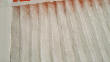
Liquid coolant is delivered to the modules and combiner from a single intake port inside the transmitter and then, after circulating, exits from a single outlet port. Both ports are connected to industrial-rated hoses that make your car radiator hoses look like toys by comparison. Fig. 1 shows a cross-section of such a hose.

KEEPING IT RUNNING
So what are your regular maintenance tasks regarding the liquid cooling inside the transmitter? None. Plain and simple. You still want to make sure the electronics and RF systems are working as expected, as with any transmitter, but since a liquid-cooled transmitter has no fans for amplifiers, no fans for power supplies and no general cabinet exhaust fans, there are no fans to check, bearings to replace or filters to clean or change.
It can’t be that easy, though. What about the other parts of the liquid cooling system? Besides the hoses, there are two additional components: the pump stand and the heat exchanger. Let’s look at required maintenance on those items, starting with the pump stand.

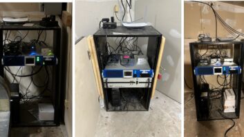
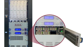
Your pump stand will typically have two fully redundant pumps per cabinet, and a cabinet can run up to 40 kW of FM power, so if one fails, the other can pick up the entire load and you remain on the air at full power. Fig. 2 shows a pump stand for a 40 kW transmitter, and Fig. 3 shows the input and output connections to the stand.
Typical maintenance on the pump stand is to change or clean the liquid filter at the pump stand once per lifetime, at about the one-year mark of operation. Since it’s a closed system, you’re not likely to have any contamination in the fluid after any possible flakes and grit left over from manufacturing are removed with the first filter cleaning, so one time will typically do it.

About once a year or so, you should check the pH level of the liquid coolant and check the level of the coolant, and that happens at the pump stand too. Again, it’s a closed system, so the level should be static, and unless there is an atypical degradation of the liquid coolant, the pH value should be static as well.

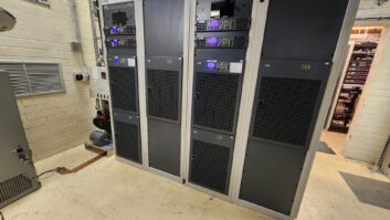
The heat exchanger, generally mounted outside the transmitter building, consists of two redundant fans and is responsible for handling the exhaust heat and transferring that heat to the outside. Figs. 4 and 5 show typical heat exchangers. At least once every year, you should look at it and make sure it’s still there, but there are otherwise no annual maintenance items for the heat exchanger.

That’s pretty much your list of tasks for the first four or five years of operation. Come year four, you should make a physical examination of the pumps and the heat exchanger to make sure they are operating properly and not generating excessive noise, which could be an indication of premature wear.
A/C IS OPTIONAL
You don’t need to run your HVAC system for a liquid-cooled transmitter … or even have an HVAC system, except for any ancillary equipment or for personal comfort while working at the site. In any case, your HVAC load will be greatly reduced, and should the HVAC fail altogether, it’s now a mere inconvenience instead of a systemic failure that will take you off the air.
Of course, that translates into significant cost reductions in HVAC operation, providing an overall systemic efficiency improvement of around 13 percent compared to current air-cooled transmitters, and even more when compared to legacy air-cooled transmitters.
The SNMP/GUI interface of your liquid-cooled transmitter will alert you to issues that may come up with the integral cooling system, so you’ll be alerted should there be any performance issues or degradation of performance.

LIQUID ODDITIES
There are some unusual things that you’ll want to be aware of with liquid-cooled transmitters.
First, they are very quiet. So quiet that in some cases you might not realize they’re actually running unless you look at the status lights on the modules or the control panel interface. The typical noise thrown off by a 40 kW THR9 transmitter is less than a 1RU Dell file server! Fig. 6 shows a THR9 installation at an FM station in Idaho.
Second, not only are the pumps quiet, too, but the heat exchangers are deceptively slow in operation. Many engineers look at the rotational speed of the heat exchangers and think there must be a fault because they’re not spinning really fast. Rest assured, if they need to spin really fast, they will. A well-designed liquid cooling system has plenty of headroom, so looking at it running in a normal ambient temperature situation will make you think it’s just loafing along … and it probably is, but it’s getting the job done.
Third, the coolant used in liquid-cooled transmitters is generally a 60/40 blend of water and a glycol compound that has some special characteristics that prevent it from leaching or damaging the metals that the coolant contacts in the heat sinks and throughout the system. You will typically have been provided with extra coolant to keep on hand should it be required, but remember, it’s a closed-loop system, so you likely won’t have to mess with it — ever.
Finally, it’s important to note that not all liquid-cooled transmitters share all of these characteristics, although most share many of the important ones. Not all liquid-cooled transmitters have liquid-cooled power supplies and combiner, which means that these designs do require HVAC, albeit at a lower level than a fully air-cooled transmitter. They also require inspection of the fans that cool these power supplies, which is more work, but still not quite as much as with an air-cooled transmitter.
Liquid cooling can be done at any power level, but is most cost-effective at higher power levels, typically 10 kW and above. Liquid cooling saves a lot of money by reducing HVAC expenses and running more efficiently, but at 1 kW, for instance, reducing your power bill by 13 percent doesn’t have the same impact that it does at 40 kW. Especially since the liquid cooling infrastructure is pretty much the same at all power levels, other than increasing the size and capacity of pumps and heat exchangers, so in low-power applications, your return on investment could be decades instead of much shorter periods typical in higher power installations.
With fewer engineers available these days and more demands being placed on them, transmitters like the THR9 from Rohde & Schwarz have integrated advanced technologies like full liquid cooling that not only reduce operational costs but also cut down on maintenance tasks to help keep station costs down and engineers sane and able to have lives outside of work. We think that’s a noble goal.
Prior to joining Rohde & Schwarz, the author worked for Broadcast Electronics and ENCO Systems; he also has been an air personality, production director, general manager and chief engineer.